Intelligent lift speed reducing belt

A deceleration belt, intelligent technology, applied in the field of intelligent lifting deceleration belt, can solve the problem of not being able to decelerate the vehicle, and achieve the effect of strong practicability, simple structure and good warning effect

Inactive Publication Date: 2012-04-25
白风宇
View PDF6 Cites 40 Cited by
  • Summary
  • Abstract
  • Description
  • Claims
  • Application Information

AI Technical Summary

Problems solved by technology

At present, the height of the deceleration strips arranged laterally on the road surface is fixed, and they all have the same deceleration effect on vehicles passing by at different speeds. They cannot decelerate the vehicles according to the speed of the vehicles. severe deceleration

Method used


Image

  • Intelligent lift speed reducing belt
  • Intelligent lift speed reducing belt
  • Intelligent lift speed reducing belt

Examples


Embodiment Construction

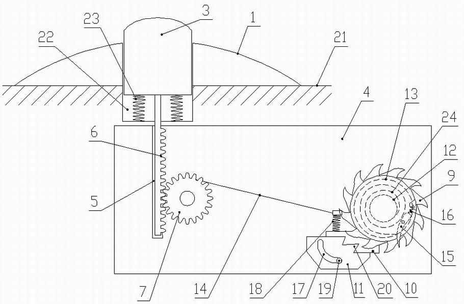
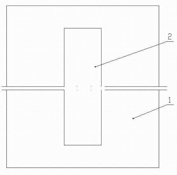
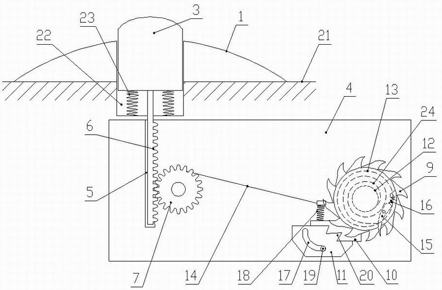
[0012] Such as figure 1 and figure 2 As shown, the intelligent lifting deceleration belt of the present invention includes a deceleration pad 1, and the middle part of the deceleration pad 1 is provided with a long hole 2 along the length direction. The cross-section of the upper surface of the module 3 is a circular arc structure, and the lower part of the lifting module 3 is connected with a lifting control device through transmission.

[0013] The lifting control device includes a bracket 4, on which a rack 6 vertically slidingly connected through a vertical slideway 5, a gear 7 meshing with the rack 6, a centrifugal clutch, a ratchet 9, a cam 10 and a fixed seat are provided. 11. The centrifugal clutch includes a spool 12 and a disc 13. The central axis of the spool 12 and the gear 7 is tightly connected by a pull cord 14. A swing rod 15 is hinged on the disc 13, and one end of the swing rod 15 extends outside the disc 13 ( The initial state of the swing rod 15 is to sh...


PUM


Abstract

The invention discloses an intelligent lift speed reducing belt, comprising a speed reducing pad. A long strip hole is formed in the middle of the speed reducing pad along a length direction, a lift module is arranged in the long strip hole, the cross section of the upper surface of the lift module is of an arc structure, and a lift control device is in transmission connection with the lower part of the lift module. The intelligent lift speed reducing belt is novel in design, simple in structure, high in practicality and easy to promote and apply, is used for correspondingly reducing the speed of a vehicle according to the running speed of the vehicle and particularly and strictly reducing the speed of the vehicle in allusion to the vehicle running at high speed, and has a good effect of warning a driver.

Description

technical field [0001] The invention relates to a traffic safety device, in particular to an intelligent lifting deceleration belt installed on a highway. Background technique [0002] With the continuous and rapid development of our country's economy, the highway transportation industry has also developed rapidly, but the traffic accident rate has also increased. Traffic safety has become a serious social problem. In order to prevent the occurrence of traffic accidents as much as possible, traffic departments or enterprises and institutions set up a row of special road sections such as road intersections, school intersections, garden districts, parking lots, and expressway toll stations. Or a few rows of speed bumps to remind or forcibly reduce the speed of passing vehicles, which plays a good role in prevention and warning, and fully reduces potential safety hazards. At present, the height of the deceleration strips arranged laterally on the road surface is fixed, and the...

Claims


Application Information

Patent Timeline
Patent Type & Authority Applications(China)
IPC IPC(8): E01F9/047E01F9/529
Inventor 白风宇
Owner 白风宇
Why Eureka
Try Eureka