Cooler for an aircraft cooling system, aircraft cooling system and method for operating an aircraft cooling system

A technology of cooling system and cooler, applied in the cooling system of power plant, auxiliary power equipment, aircraft parts, etc., can solve the problems of increasing fuel consumption, increasing air resistance, high pressure loss, etc., to improve cooling capacity , the effect of small pressure loss and small weight

Active Publication Date: 2014-07-16
AIRBUS OPERATIONS GMBH
View PDF5 Cites 0 Cited by
  • Summary
  • Abstract
  • Description
  • Claims
  • Application Information

AI Technical Summary

Problems solved by technology

However, both the air intake and the air outlet are formed on the aircraft skin, which increases air resistance and thus increases fuel consumption
In addition, aircraft cooling systems that supply cooling air through ram air inlets have high pressure losses, cooling capacity is limited by the maximum air supply flow rate of said ram air inlets, and are relatively high in weight

Method used


Image

  • Cooler for an aircraft cooling system, aircraft cooling system and method for operating an aircraft cooling system
  • Cooler for an aircraft cooling system, aircraft cooling system and method for operating an aircraft cooling system
  • Cooler for an aircraft cooling system, aircraft cooling system and method for operating an aircraft cooling system

Examples


Embodiment Construction

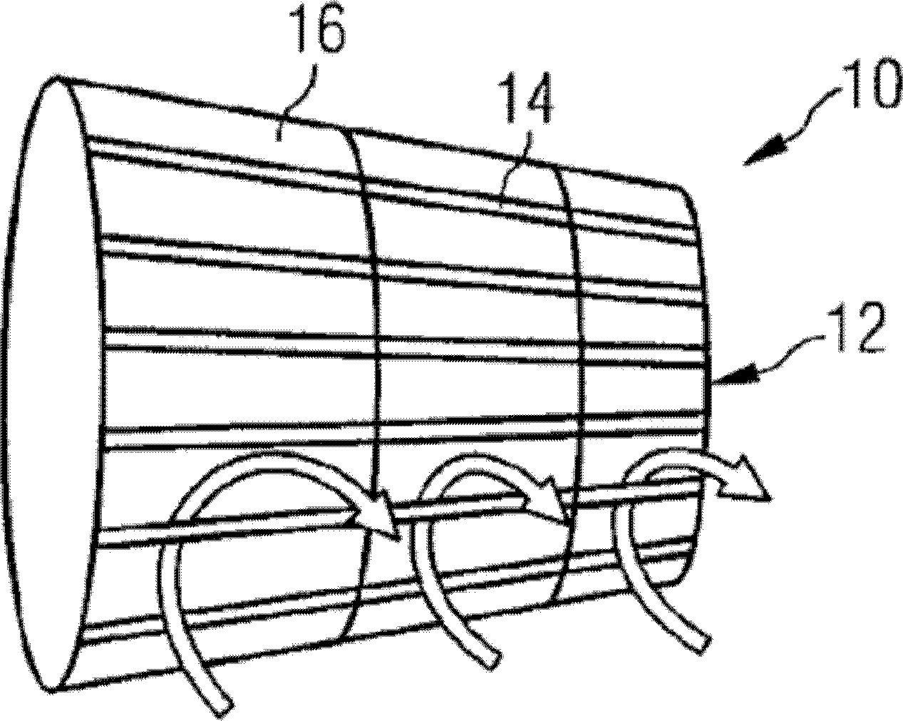
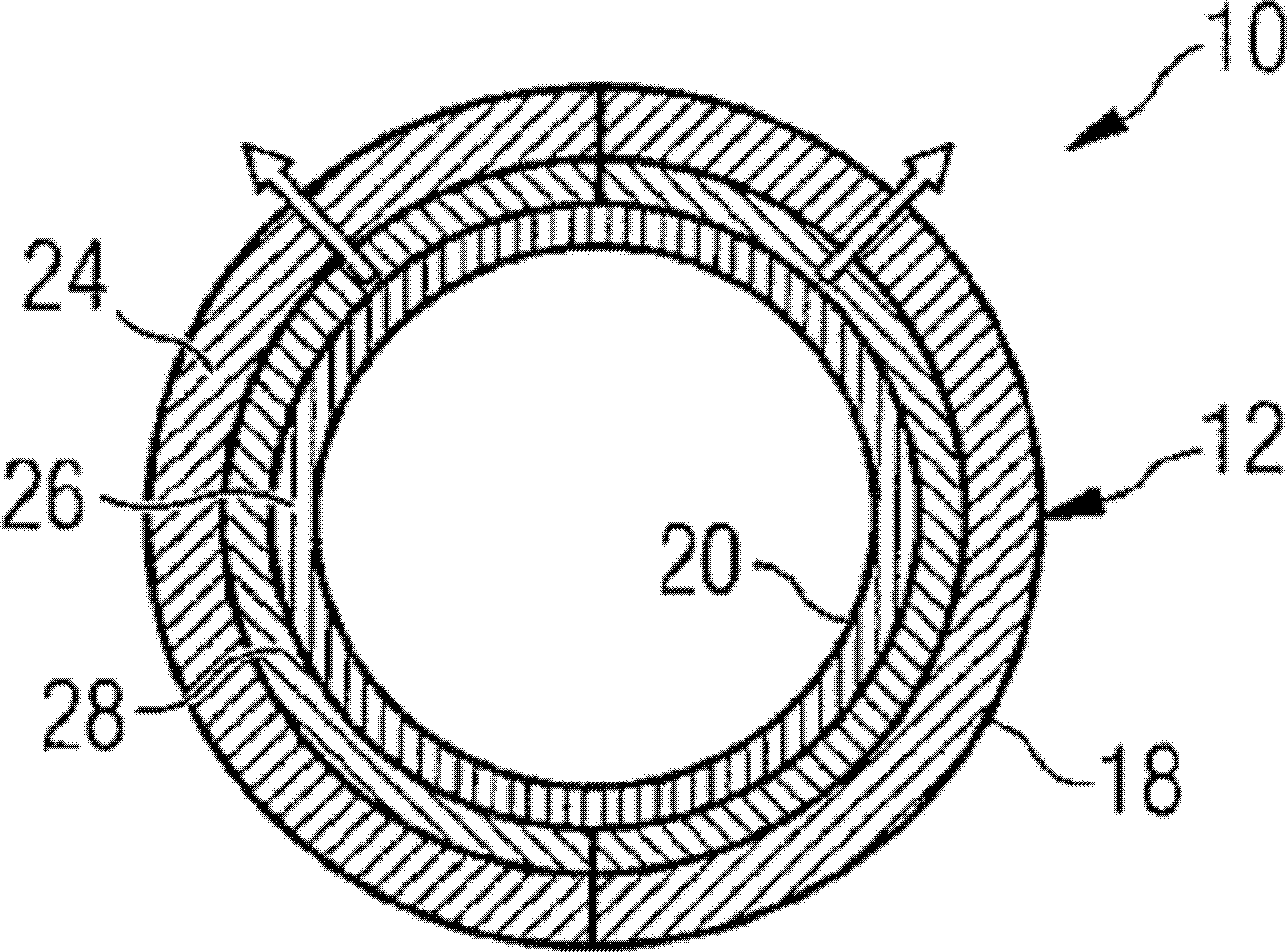
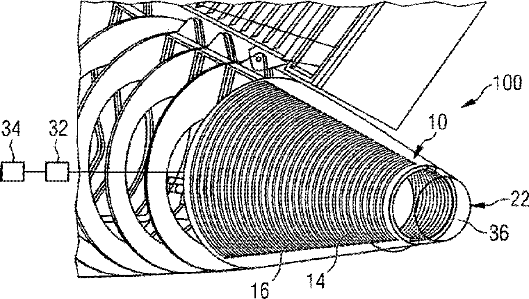
[0066] Figure 1 to Figure 3 Shown applicable to aircraft cooling system 100 (see Figure 7 to Figure 13 and Figure 15 Shown) is a first embodiment of the cooler 10 . Figure 1 to Figure 3 The illustrated cooler 10 includes a base 12 that includes a plurality of layers 14, such as Figure 1 to Figure 3 Schematically shown. The plurality of plies 14 define a plurality of coolant passages 16 extending from the first surface 18 of the substrate 12 to the second surface 20 of the substrate 12 (see figure 2 ).

[0067] The shape of the base body 12 of the cooler 10 is a hollow conical shape with the top truncated, specifically as image 3 As shown, the base body 12 is designed to form a region of the aircraft skin adjacent to the aircraft tail end 22 . That is to say, the base body 12 of the cooler 10 replaces the aircraft skin present in other areas of the aircraft in the area of ​​the aircraft adjacent to the rear end 22 . Thus, in the installed state of the cooler 10 on...


PUM


Abstract

The invention relates to a cooler (10) of an aircraft cooling system (100). The cooler includes a base body (12), on which a plurality of coolant passages (16) are designed, and the coolant passages extend from the base body ( The first surface (18) of 12) extends to the second surface (20) of the base body (12) to allow coolant to flow through said base body (12). The base body (12) of the cooler is designed to form part of an aircraft skin.

Description

technical field [0001] The invention relates to a cooler for an aircraft cooling system, an aircraft cooling system incorporating the cooler and suitable for cooling, for example, a fuel cell system used in an aircraft, and a method of operating the aircraft cooling system. Background technique [0002] Fuel cell systems can generate electricity with low emissions and high efficiency. Therefore, efforts are being made to employ fuel cell systems to generate electricity in various mobile applications such as automotive engineering or aviation. For example, it is conceivable to use a fuel cell system in an aircraft to replace the generators currently used to generate electricity in aircraft, driven by the main engine or an auxiliary power unit (APU). In addition, the fuel cell system could also be used to supply emergency power to the aircraft and replace the ram air turbine currently used as the emergency power system. [0003] When the fuel cell is working, it not only gen...

Claims


Application Information

Patent Timeline
Patent Type & Authority Patents(China)
IPC IPC(8): F28D1/04B64D33/10B64D41/00
CPCY02T50/44F28D2001/0266Y02T90/36B64D33/10B64D41/00F28D1/04F28D2021/0078B64D2041/005F28F13/06F28F13/003F28F7/02Y02T50/40Y02T90/40
Inventor T·鲍姆加特R·施托尔特C·韦伯R·雷瑙迪C·米勒
Owner AIRBUS OPERATIONS GMBH
Why Eureka
Try Eureka