Component measuring device

A component measurement and installation technology, which is applied to measuring devices, analysis materials, diagnostic records/measurement, etc., can solve problems such as measurement errors and changes in data volume, and achieve the effects of improving measurement accuracy and reducing measurement errors

Active Publication Date: 2012-05-02
TERUMO KK +1
View PDF10 Cites 6 Cited by
  • Summary
  • Abstract
  • Description
  • Claims
  • Application Information

AI Technical Summary

Problems solved by technology

As a result, there are following problems in the conventional component measuring device: Since the diameter of the irradiation light spot and the illuminance distribution in each device are changed, the amount of data obtained by each device will change, and there will be differences between devices. Measurement error occurs

Method used


Image

  • Component measuring device
  • Component measuring device
  • Component measuring device

Examples


Embodiment Construction

[0022] Below, refer to Figure 1 to Figure 10 An embodiment example of the component measuring device of the present invention will be described. In addition, in each figure, the same code|symbol is attached|subjected to the common component. In addition, the present invention is not limited to the following aspects.

[0023] In addition, description will be performed in the following order.

[0024] 1. Configuration example of component measuring device

[0025] 2. Operation of the component measuring device

[0026] 1. Configuration example of component measuring device

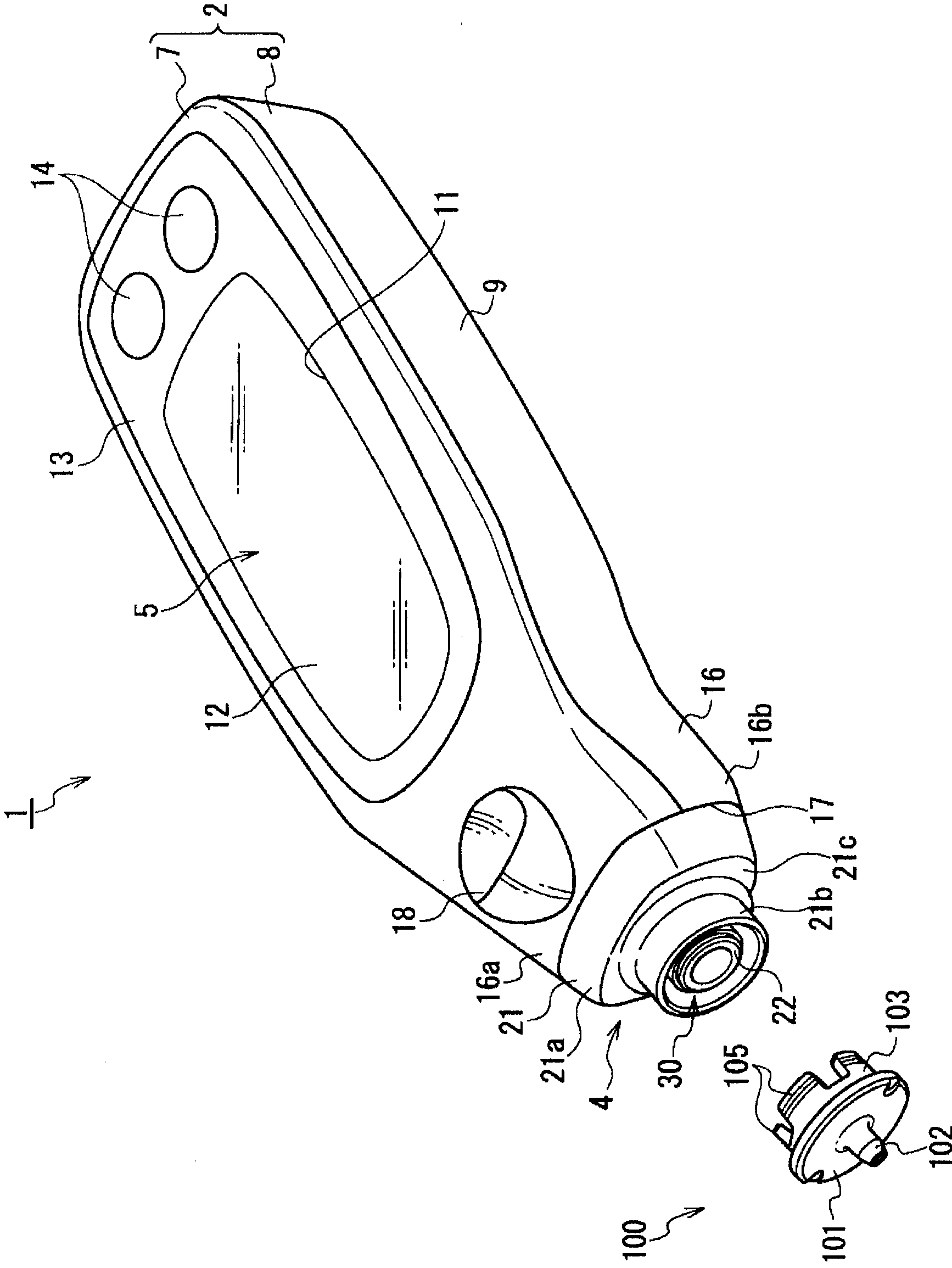
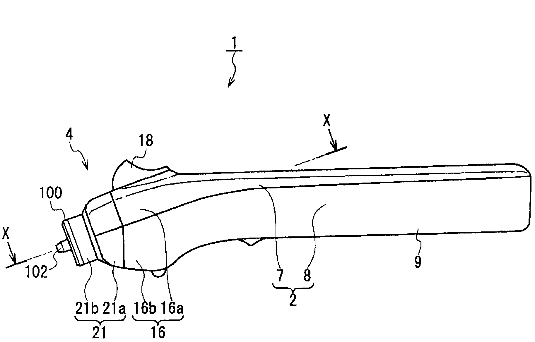
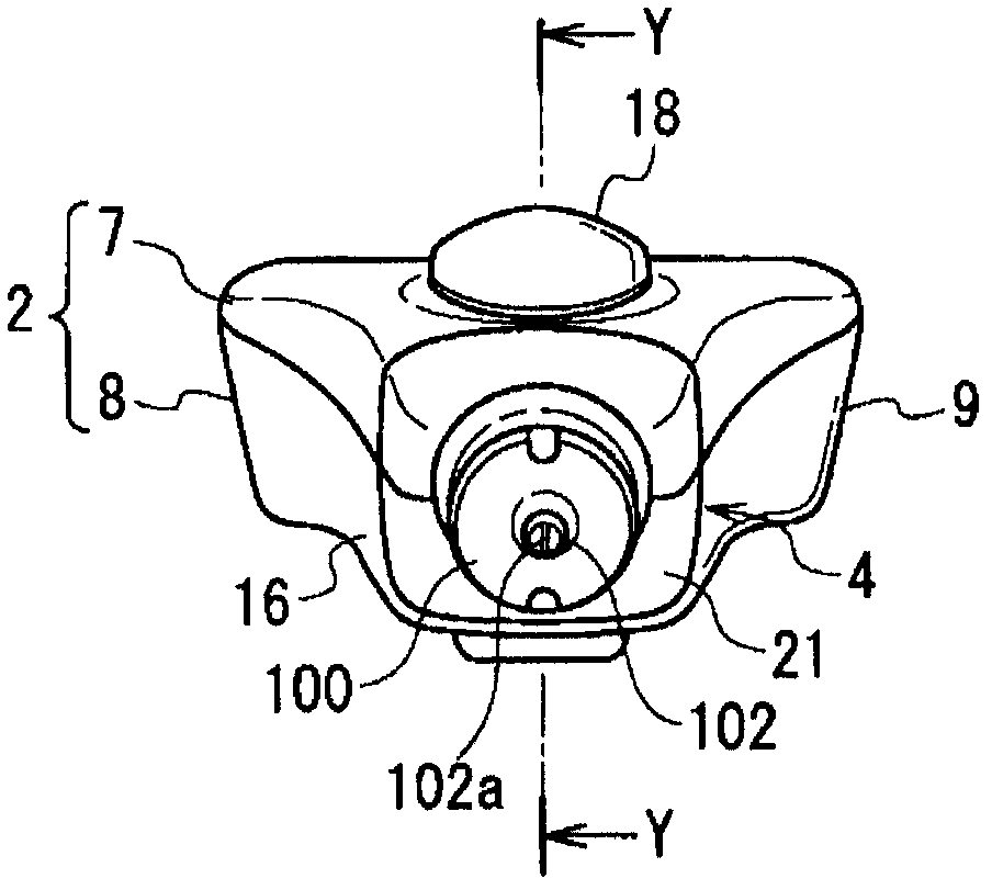
[0027] First, refer to Figure 1 ~ Figure 3 The configuration of a blood glucose level measurement device applied as a component measurement device according to an embodiment of the present invention (hereinafter referred to as "this example") will be described.

[0028] figure 1 is a perspective view showing the blood glucose level measuring device of this example, figure 2 is a right side view sh...


PUM


Abstract

Disclosed is an arrangement wherein light can be efficiently radiated to test papers even if a light source with a small amount of light is used, and wherein diameters of radiation spots projected onto test papers, as well as luminance distributions, can be adjusted. This arrangement is provided with an installation section (30) in which a tip (100) is installed, a light source (80a) which emits light having a specified wavelength, and a light receiving element (44) which receives light reflected from a test paper (107). Furthermore, the arrangement is provided with a condensing lens (53) which the moment that the light emitted by the light source comes in, concentrates the light on the test paper (107), and an optical path block (26). The optical path block (26) is equipped with an aperture section (66) which is located between the condensing lens (53) and the light source (80a) and which is installed at the position of the photographic subject for the condensing lens (53).

Description

technical field [0001] The present invention relates to a component measurement device for optically measuring blood glucose levels, urine components, or predetermined components in liquids such as waste water and industrial water. Background technique [0002] Conventionally, in order to detect chemical components in body fluids and industrial water, and to measure the amount and properties of specified components, component measuring devices that optically measure specified components have been used. The component measuring device first impregnates a test paper with liquid such as blood, and irradiates the test paper with light having a predetermined wavelength. Then, by measuring the intensity of reflected light reflected from the test paper, predetermined components in the measurement liquid are calculated and measured (for example, refer to Patent Document 1). [0003] In addition, Patent Document 2 describes a technique in which two light sources having different wave...

Claims


Application Information

Patent Timeline
Patent Type & Authority Applications(China)
IPC IPC(8): G01N21/78A61B5/1455G01N21/27
CPCA61B5/14546G01N21/8483A61B5/1455A61B5/14532
Inventor 西内大祐相川亮桂浅野光宏岩城禄宪
Owner TERUMO KK
Why Eureka
Try Eureka