Positioning device for workbench

A positioning device and workbench technology, which is applied in the direction of manufacturing tools, metal processing equipment, metal processing machinery parts, etc., can solve the problems of frequent alarms in the pneumatic detection of the workbench, and achieve the effect of simple structure, high degree of combination, and simple movement mode

Inactive Publication Date: 2012-05-16
SANY GRP
View PDF8 Cites 9 Cited by
  • Summary
  • Abstract
  • Description
  • Claims
  • Application Information

AI Technical Summary

Problems solved by technology

[0003] In view of the above existing problems, the purpose of the present invention is to provide a worktable positioning device, so as to solve the problem of frequent pneumatic detection alarms caused by s

Method used


Image

  • Positioning device for workbench
  • Positioning device for workbench
  • Positioning device for workbench

Examples


Embodiment Construction

[0020] The present invention will be further described below in combination with principle diagrams and specific operation examples.

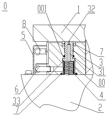
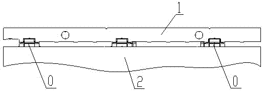
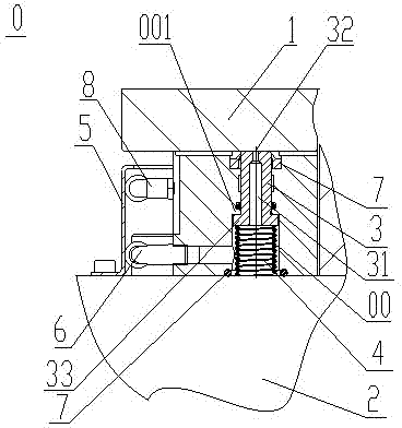
[0021] like figure 1 As shown, the workbench positioning device of the present invention includes several positioning blocks 0 arranged between the workbench part 1 and the workbench base 2, the positioning block 0 can also be installed on the intermediate body, and the positioning block 0 is provided with a through hole cavity 00, fill a piston 3 in the through hole cavity 00, the lower end of the piston 3 is movably supported up and down on the surface of the workbench base 2 through an elastic component 4, and the elastic component 4 is specifically a spring. A gas detection through hole (not marked in the figure) is set horizontally on the inner side of the through hole chamber 00, the gas detection through hole is externally connected to the first gas pipe joint 6, a gas detection channel 31 is opened in the piston 3, and a gas detection c...


PUM


Abstract

The invention discloses a positioning device for a workbench. The positioning device comprises a plurality of positioning blocks arranged between a workbench component and a workbench base, wherein through hole cavities are formed in the positioning blocks; pistons are arranged in the through hole cavities; the lower end of each piston is supported on the surface of the workbench base up and down in a movable mode by an elastic component; air detection through holes are formed on one side in the through hole cavities; air detection channels are formed in the pistons; air detection interfaces are formed on surfaces of the tops of the pistons; step structures are arranged inside the through hole cavities; bulged structures are arranged at bottoms of the pistons; when the bulged structures at the bottoms of the pistons are pressed against the step structures arranged inside the through hole cavities, the top ends of the pistons are bulged to a certain distance from the surfaces of the positioning blocks; and when the workbench is clamped and positioned, the surface of the tops of the pistons is tightly attached to the surface at the bottom of the workbench component tightly. The positioning device for the workbench has a simple structure, few application parts, a simple motion mode and high reliability and combination degree, modularized installation can be realized, and the detection effect of clamping the workbench is improved effectively.

Description

technical field [0001] The invention relates to the technical field of clamping and positioning, in particular to a workbench positioning device. Background technique [0002] At present, machine tools with movable worktables occupy a large part of the market demand. The movable worktables often need to be fixed during processing, so a clamping positioning mechanism is produced. The clamping mechanism commonly used in the market is to pull down through hydraulic pressure. Tightening workbench, such as Chinese patent CN 201067844Y discloses a positioning and clamping compound mechanism for exchanging worktables of large and medium-sized horizontal processing machine tools, which is mainly composed of tensioning oil cylinder and positioning tensioning oil cylinder. The tension of the oil cylinder is fed back by detecting the stroke of the oil cylinder piston, but it is impossible to detect the combination of the workbench and the positioning surface after the workbench positio...

Claims


Application Information

Patent Timeline
IPC IPC(8): B23Q17/00
Inventor 蒙昌钱王斌王海波
Owner SANY GRP
Why Eureka
Try Eureka