Locking device used for lifter

A lift and self-locking technology, which is applied in the field of lifts, can solve the problems of reducing work efficiency and achieve the effect of improving the efficiency of locking and unlocking

Inactive Publication Date: 2015-04-15
LAIWU IRON & STEEL GRP
View PDF3 Cites 0 Cited by
  • Summary
  • Abstract
  • Description
  • Claims
  • Application Information

AI Technical Summary

Problems solved by technology

Since the lifting platform 03 is locked and unlocked manually, the work efficiency is greatly reduced

Method used


Image

  • Locking device used for lifter
  • Locking device used for lifter
  • Locking device used for lifter

Examples


Embodiment Construction

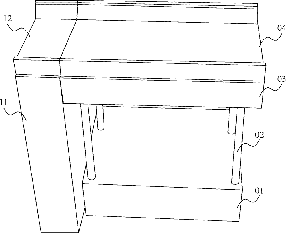
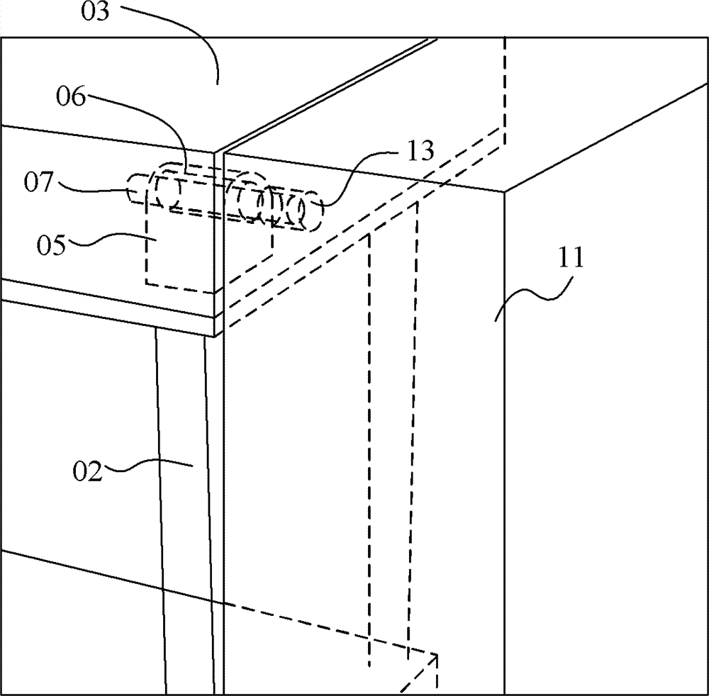
[0040] The invention discloses a locking device for an elevator, which is used to improve the locking and unlocking efficiency of the lifting platform in the elevator and reduce the efficiency.

[0041] The following will clearly and completely describe the technical solutions in the embodiments of the present invention with reference to the accompanying drawings in the embodiments of the present invention. Obviously, the described embodiments are only part of the embodiments of the present invention, not all of them. Based on the embodiments of the present invention, all other embodiments obtained by persons of ordinary skill in the art without making creative efforts belong to the protection scope of the present invention.

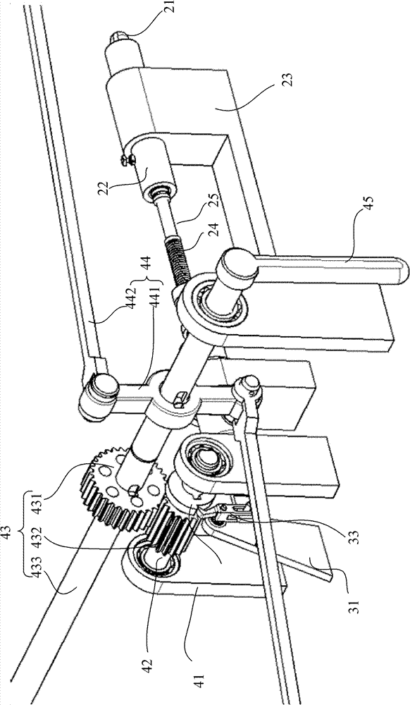
[0042] Such as image 3 , Figure 9 and Figure 10 As shown, the locking device disclosed in the present invention includes an actuator that outputs reciprocating linear motion thrust; and a self-locking device that controls the start and reversing of ...


PUM


Abstract

The invention discloses a locking device used for a lifter. The locking device comprises an actuator for outputting a reciprocated rectilinear motion pushing force, and a self-locking device for controlling the starting and the reversing of the actuator. When in use, one end of a pin shaft is mounted at the output end of the actuator, and the other end of the pin shaft corresponds to a mounting hole formed on a side wall. When a lifting platform rises until the lifting platform and the side wall have the same height, by controlling the self-locking device, the actuator is driven to output and push the pin shaft to move in the direction close to the side wall until the other end of the pin shaft is inserted into the mounting hole corresponding to a through hole, so as to lock the lifting platform. When the lifter is under normal work, the self-locking device drives the actuator to push the pin shaft to move in the direction far away from the side wall until the other end of the pin shaft is pushed out of the mounting hole on the side wall completely, so as to achieve the unlocking of the lifting platform. Since the unlocking and locking actions of the locking device are controlled mechanically, the locking and unlocking efficiencies of the platform in the lifter can be improved.

Description

technical field [0001] The invention relates to the technical field of elevators, and more specifically, to a locking device for elevators. Background technique [0002] The fixed lifting platform is a kind of cargo lifting equipment with good lifting stability and wide application range. In locomotive, automobile maintenance and other fields, elevators are generally used to lift and lower the single axle of the traveling wheel to cooperate with the maintenance line. Such as figure 1 As shown, the large elevator includes a lifting mechanism 02, a lifting platform 03, a base 01, a fixed track 04, a controller and a driving mechanism (not shown in the figure), wherein the lifting mechanism 02 is arranged between the base 01 and the lifting platform 03 , and is driven by the drive mechanism, the fixed track 04 is set on the lifting platform 03; the controller controls the drive mechanism to open or close. When the lifter is carrying out the lifting operation, the lifting mec...

Claims


Application Information

Patent Timeline
Patent Type & Authority Patents(China)
IPC IPC(8): B66F7/28
Inventor 刘智杨刚段崇义孟东邵学
Owner LAIWU IRON & STEEL GRP
Why Eureka
Try Eureka