LED (Light-emitting Diode) fluorescent tube

A technology of LED fluorescent lamps and lamps, applied in the field of LED lighting, can solve problems such as inability to install at will

Active Publication Date: 2014-09-03
BEIJING ITSYNC TECH
View PDF7 Cites 0 Cited by
  • Summary
  • Abstract
  • Description
  • Claims
  • Application Information

AI Technical Summary

Problems solved by technology

[0006] In view of this, the main purpose of the present invention is to provide an LED fluorescent tube to solve the problem that the LED fluorescent tube cannot be installed at will in the prior art

Method used


Image

  • LED (Light-emitting Diode) fluorescent tube
  • LED (Light-emitting Diode) fluorescent tube
  • LED (Light-emitting Diode) fluorescent tube

Examples


Embodiment Construction
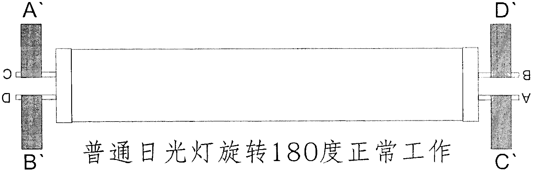
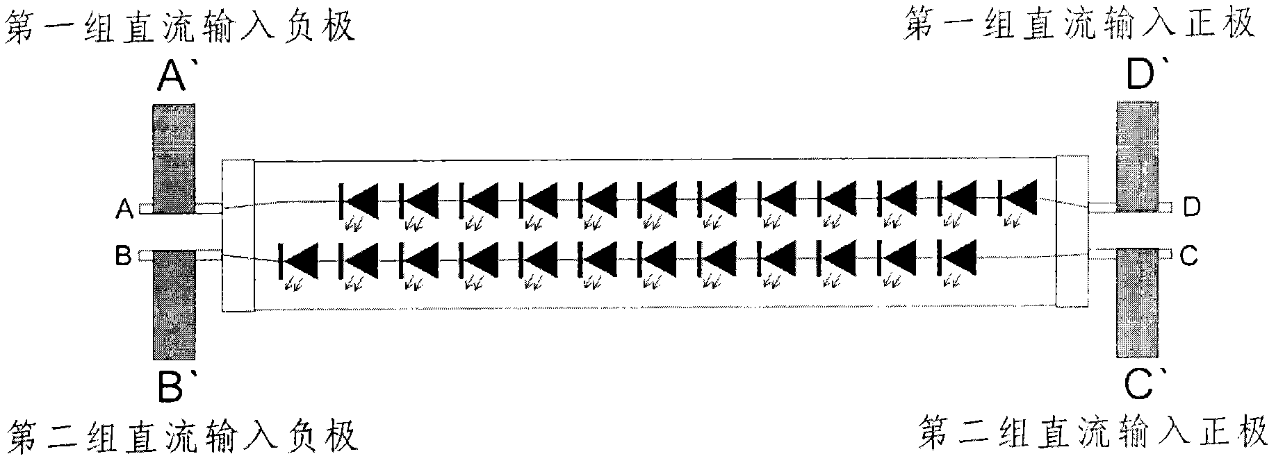
[0040] The basic idea of ​​the present invention is: by wiring a pair of lines of the same type (a pair of power signal lines or a pair of control signal lines) in a diagonal manner, that is, arranging the two poles of the power signal in a diagonal manner On the two terminals of the lamp shell, at the same time, the two poles of the control signal are arranged on the other two terminals of the lamp shell in a diagonal manner, and by setting a rectifier circuit inside the LED lamp shell, to Realize the random installation of LED fluorescent tubes.

[0041] The implementation of the present invention will be described in detail below with reference to the drawings and in combination with the embodiments.

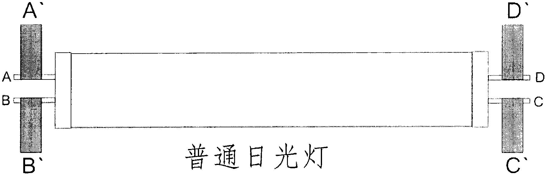
[0042] Figure 5A The wiring method of the LED fluorescent tube according to the embodiment of the present invention is shown. Such as Figure 5A As shown, the LED fluorescent tube of the embodiment of the present invention comprises:

[0043] A lamp housing with four ter...


PUM


Abstract

The invention discloses an LED (Light-emitting Diode) fluorescent tube, comprising a tube shell provided with four wiring terminals, an LED light-emitting element and a rectification circuit, wherein the four wiring terminals are divided into two groups two by two and the two groups are respectively located at two ends of the tube shell and are used for receiving input signals; the LED light-emitting element is arranged in the tube shell; the rectification circuit is used for adjusting the input signals to avoid polarity reversing; and a wiring way of the four wiring terminals is arranged according to a diagonal line way. With the adoption of the LED fluorescent tube provided by the invention, the polarity problem of the LED fluorescent tube does not need to be considered and the random installation of the LED fluorescent tube is realized.

Description

technical field [0001] The present invention relates to the field of LED lighting, more specifically, to an LED fluorescent tube. Background technique [0002] With the development of light-emitting diode (Light Emitting Diode, LED) technology, LED fluorescent lamps are playing an increasingly important role in the lighting field. Because LED fluorescent lamps have many advantages, such as energy saving, long service life, and no noise, etc., More and more places have begun to use LED fluorescent lamps as lighting equipment. [0003] As we all know, a traditional fluorescent tube has four terminals, as shown in Figure 1, which are located at both ends of the fluorescent tube (two at each end). For traditional fluorescent lamps, the two terminals at each end are connected to the filament, so no matter how you install it, if Figure 1A with Figure 1B As shown, the fluorescent tubes can emit light normally. [0004] Figure 2 shows the wiring method of the existing LED fluor...

Claims


Application Information

Patent Timeline
Patent Type & Authority Patents(China)
IPC IPC(8): F21S2/00F21V19/00F21V23/06H05B37/02F21Y101/02F21K9/27F21Y115/10
Inventor 黄喜荣
Owner BEIJING ITSYNC TECH
Why Eureka
Try Eureka