Integrated motor vane pump hydraulic power unit

A technology of hydraulic power unit and vane pump, which is applied in the direction of fluid pressure actuation device, fluid pressure actuation system components, mechanical equipment, etc. It can solve the problems of complex structure of hydraulic power unit, large noise of hydraulic power unit, increased flow resistance, etc. , to achieve the effect of light weight, elimination of aerodynamic noise, and convenient cooling

Inactive Publication Date: 2012-08-08
LANZHOU UNIVERSITY OF TECHNOLOGY
View PDF7 Cites 9 Cited by
  • Summary
  • Abstract
  • Description
  • Claims
  • Application Information

AI Technical Summary

Problems solved by technology

[0002] The hydraulic power unit is the heart of the hydraulic system. At present, the hydraulic power unit with the electric motor as the driving force is a discrete structural form. The hydraulic pump is connected to the fuel tank through straight pipes, bent pipes, pipe joints, seals, stop valves and other accessories. The entire hydraulic power unit has complex structure, low efficiency, large volume and weight; There are possible external leakages at the connecting parts of the pipeline and the shaft extension of the hydraulic pump; in addition, since the independent hydraulic pump has a closed shell and is independent from the fuel tank, its oil suction port is connected to the fuel tank through pipelines, resulting in The increase of the flow resistance and the compression of the space of the oil suction chamber will cause local negative pressure in the oil suction flow channel and insufficient oil suction of the hydraulic pump, causing bubble precipitation, cavitation noise and vibration, so the noise of the entire hydraulic power unit is also very large

Method used


Image

  • Integrated motor vane pump hydraulic power unit
  • Integrated motor vane pump hydraulic power unit
  • Integrated motor vane pump hydraulic power unit

Examples


Embodiment Construction

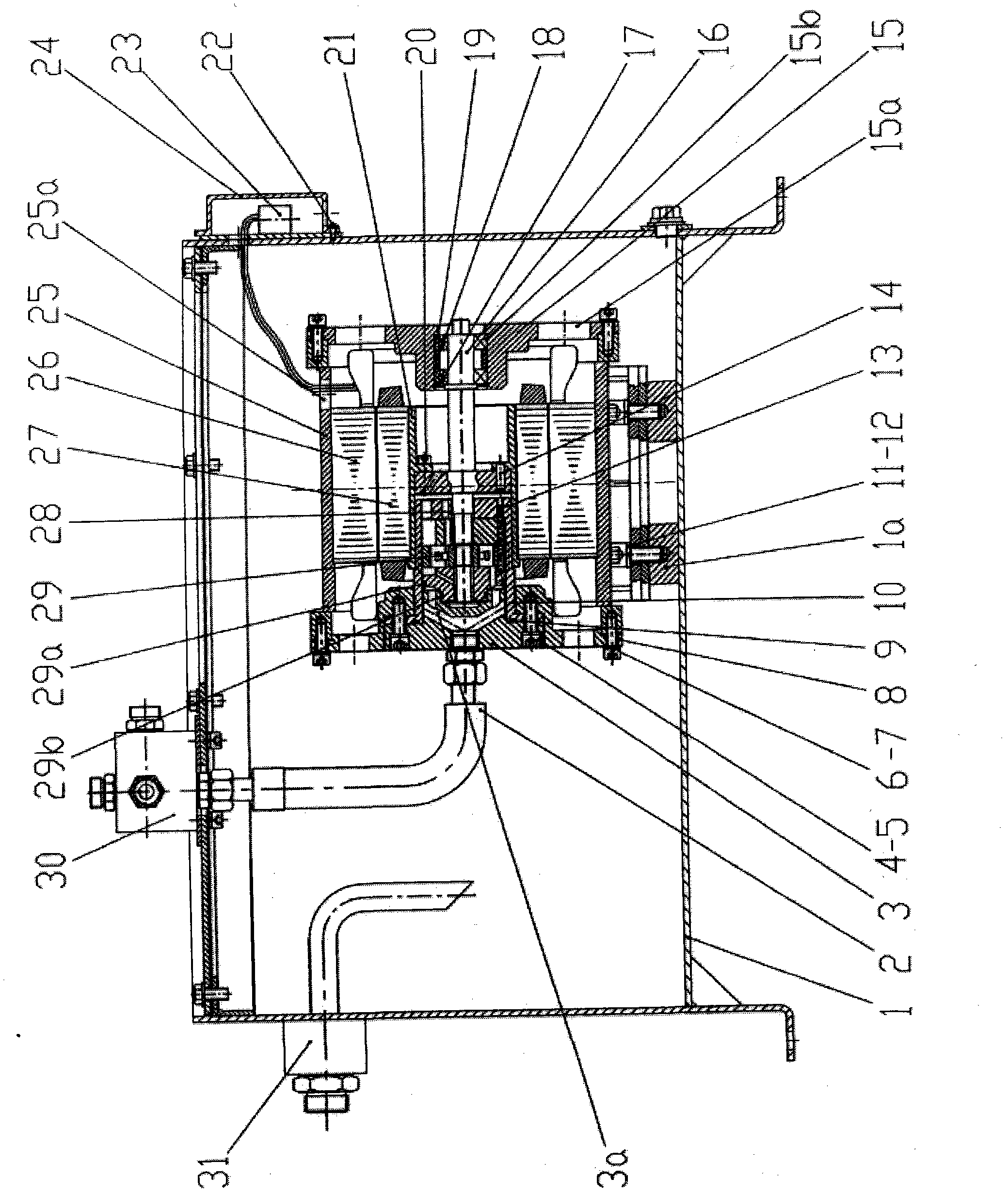
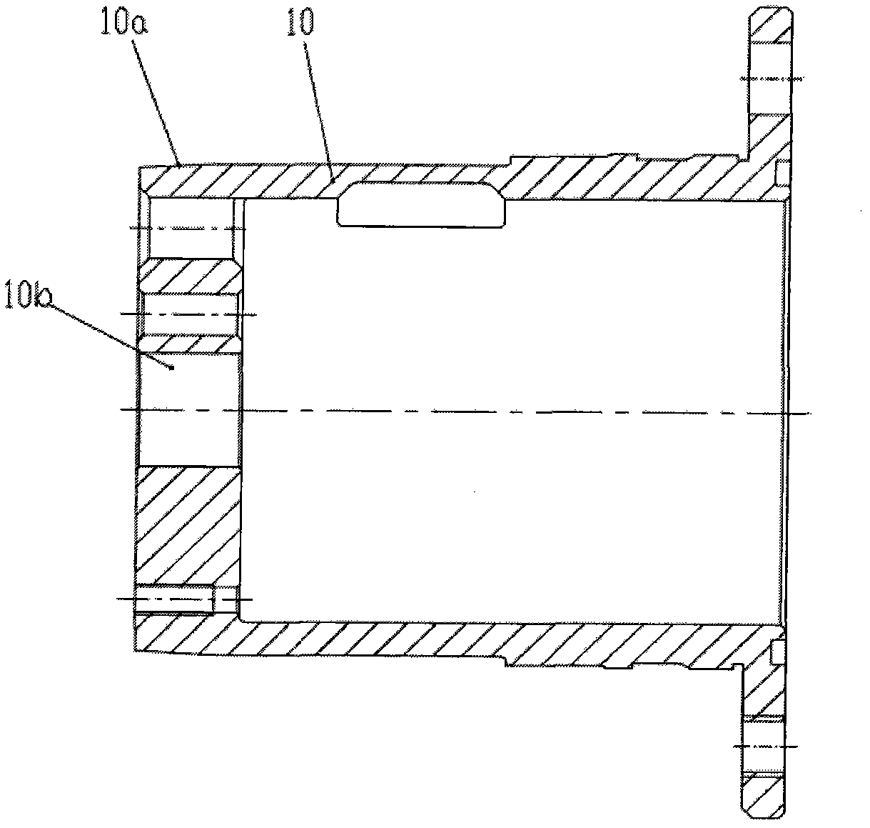
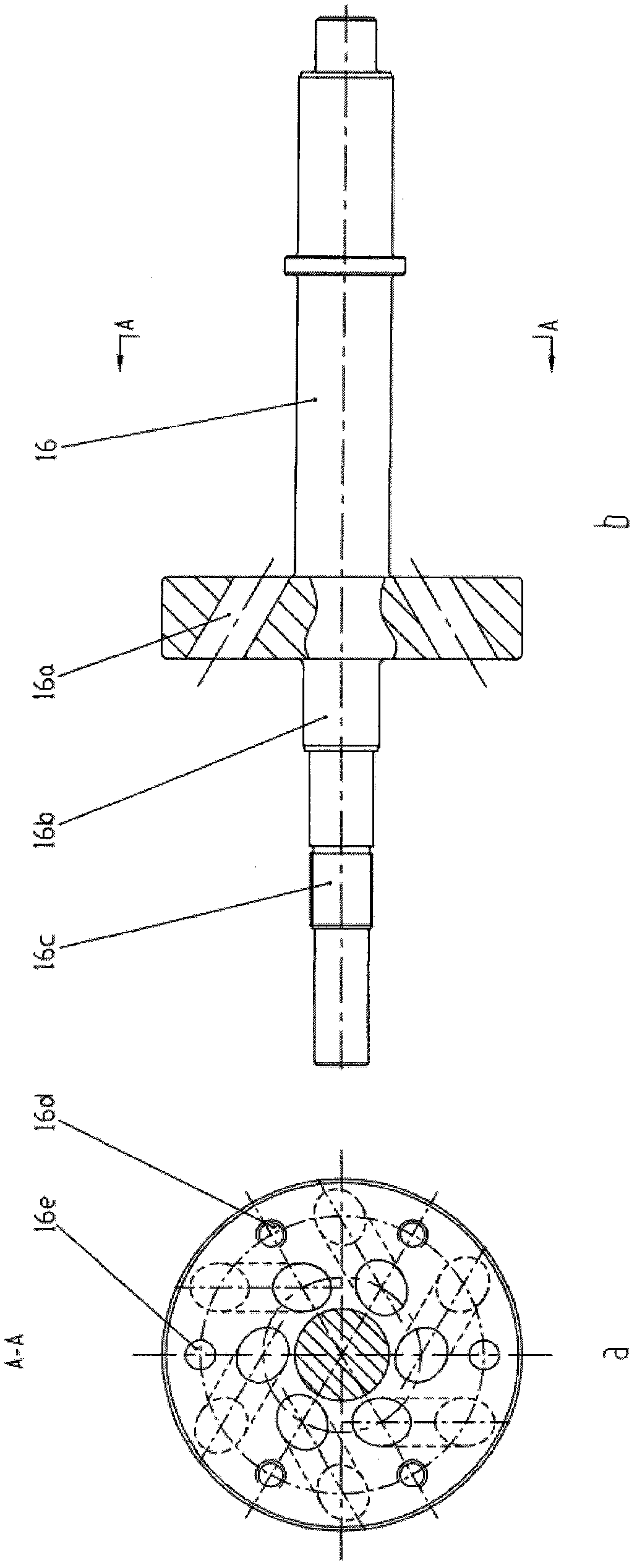
[0009] Such as Figure 1 to Figure 5 As shown, the integrated motor vane pump hydraulic power unit mainly includes a box body 1, a vane pump 29, a motor rotor 27, a motor stator 26, a high-pressure oil pipe 2, an oil return line 31, an oil block 30, and an oil outlet gland 3. Pump core seat 10, sliding bearing 28, rotor sleeve 21, main shaft 16, pump front cover 8, pump back cover 15, frame 25 and terminal 23, motor rotor 27 and rotor sleeve 21, main shaft 16 through pin 14, The fifth screw 20 is connected to form a rotor body, and is supported on the pump back cover 15 and the pump core base 10 through the sliding bearing 28 in the pump core base 10 and the two sets of rolling bearings 19 in the pump back cover 15, wherein the pump core base 10 is fixed on On the pump front cover 8, the vane pump 29 is connected to the main shaft 16 through a spline 16c, and the vane pump 29 is installed in the pump core seat 10 through the oil outlet gland 3, the first screw 4, the first was...


PUM


Abstract

The invention relates to an integrated motor vane pump hydraulic power unit. In the integrated motor vane pump hydraulic power unit, a motor rotor (27) is connected with a rotor sleeve (21) and a main shaft (16) through a pin (14) and a screw (20), so as to form a rotor body; the rotor body is supported on a pump rear cover (15) and a pump core seat (10) through a sliding bearing (28) in the pump core seat (10) and two groups of rolling bearings (19) in the pump rear cover (15); a vane pump (29) is connected with the main shaft (16) through a spline (16c); the vane pump (29) is arranged in the pump core seat (10) through an oil outlet gland (3), a screw (4), a gasket (5) and a pump front cover (8); a motor stator (26) is pressed in a motor base (25); the pump front cover (8) and the pump rear cover (15) are fixed on the motor base (25); the motor base (25) is fixed on a support (1a) in a box body (1); an oil outlet of a hydraulic pump (29) is communicated with an inner runner (3a) of the oil outlet gland (3); and the oil outlet gland is connected with an oil path block (30) on the box body (1) through a high-pressure oil pipe (2).

Description

technical field [0001] The invention relates to the field of hydraulic power units, in particular to an integrated electro-hydraulic power unit. Background technique [0002] The hydraulic power unit is the heart of the hydraulic system. At present, the hydraulic power unit with the electric motor as the driving force is a discrete structural form. The hydraulic pump is connected to the fuel tank through straight pipes, bent pipes, pipe joints, seals, stop valves and other accessories. The entire hydraulic power unit has complex structure, low efficiency, large volume and weight; There are possible external leakages at the connecting parts of the pipeline and the shaft extension of the hydraulic pump; in addition, since the independent hydraulic pump has a closed shell and is independent from the fuel tank, its oil suction port is connected to the fuel tank through pipelines, resulting in The increase of the flow resistance and the compression of the space of the oil suctio...

Claims


Application Information

Patent Timeline
Patent Type & Authority Applications(China)
IPC IPC(8): F15B21/00F15B21/04
Inventor 冀宏王金林王峥嵘王建森孙天健武俊合赵光明汪翔翎
Owner LANZHOU UNIVERSITY OF TECHNOLOGY
Why Eureka
Try Eureka