An apparatus, a method, and a computer program product for automatic focusing

A technology of equipment and timing, applied in the direction of focusing devices, sub-office equipment, cameras, etc., can solve the problems of impossible interoperability and compatibility, and achieve the effect of good compatibility

Active Publication Date: 2012-08-22
NOKIA TECHNOLOGLES OY
View PDF3 Cites 4 Cited by
  • Summary
  • Abstract
  • Description
  • Claims
  • Application Information

AI Technical Summary

Problems solved by technology

The hardware and software features of different camera modules are often very different, making interoperability and compatibility often difficult or impossible

Method used


Image

  • An apparatus, a method, and a computer program product for automatic focusing
  • An apparatus, a method, and a computer program product for automatic focusing
  • An apparatus, a method, and a computer program product for automatic focusing

Examples


example 1

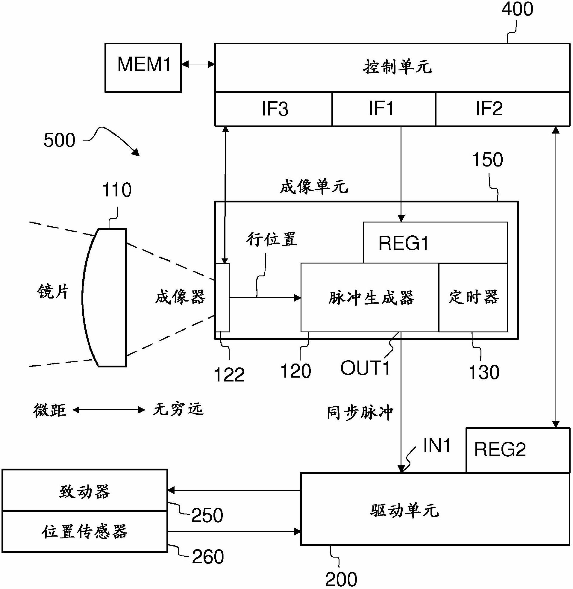
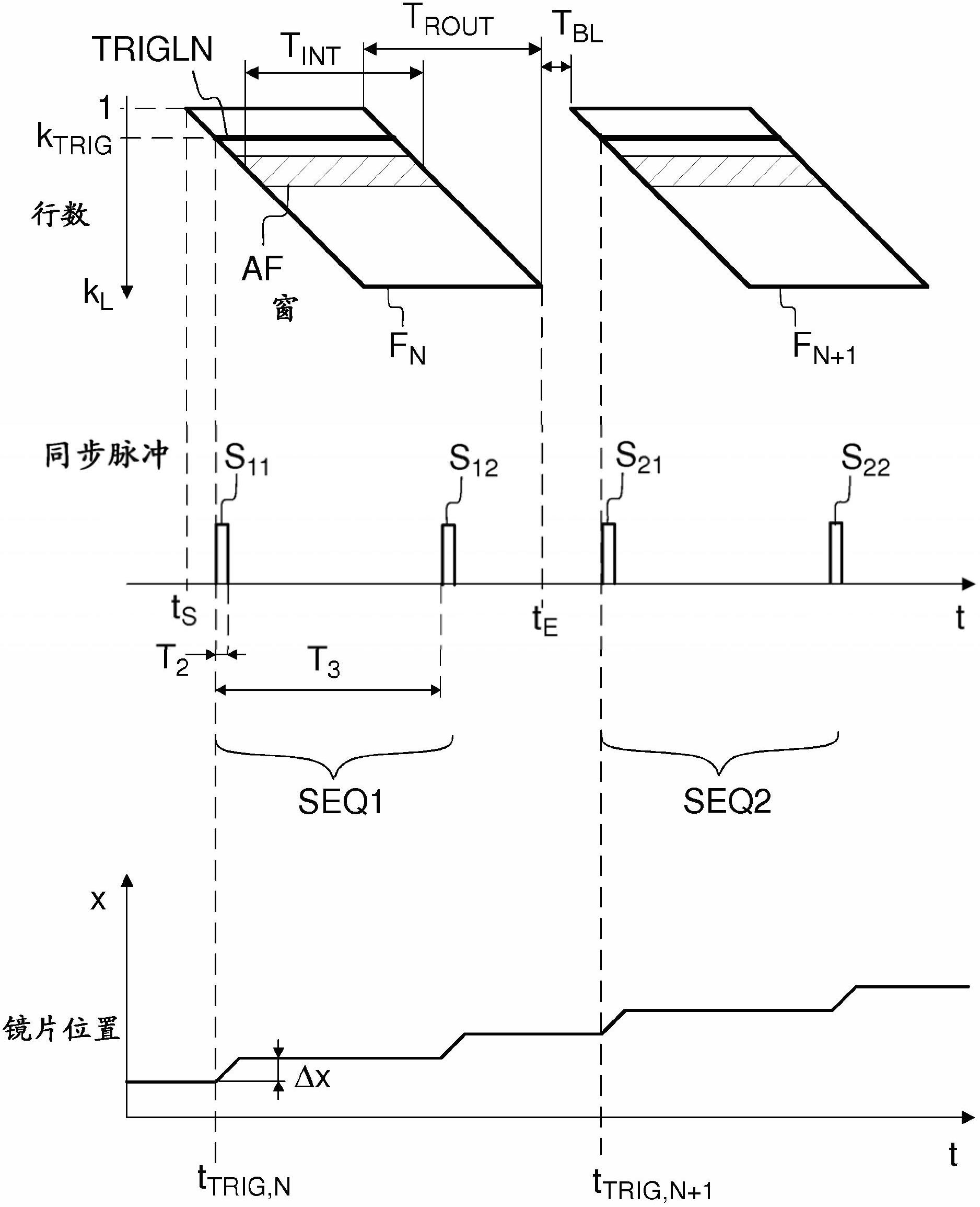
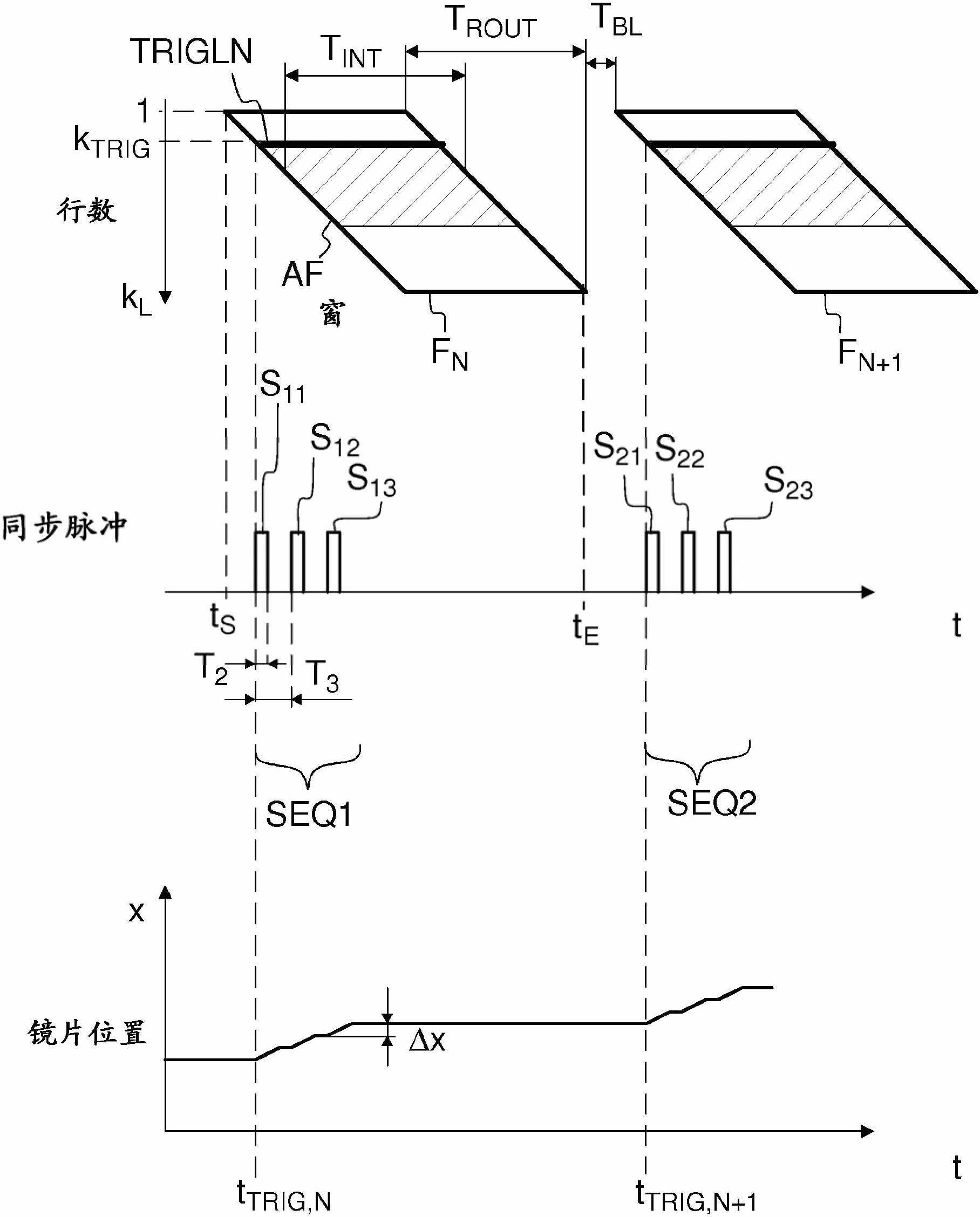
[0091] The parameters can be set as follows: Master_Trigger_Count=3, Sequence_Number=2, Strobe_Count_Phase1=3. Now, two pulse trains will be generated, where each train consists of three pulses. When the input IN1 of the drive unit 200 receives a pulse, the following happens: when no pulse is received, strobe_count_phase1 is equal to zero. strobe_count_phase1 is equal to 1 after the first pulse. After the second pulse, strobe_count_phase1 equals 2. After the third pulse, strobe_count_phase1 equals 3. After the fourth pulse, strobe_count_phase1 equals 1. After the fifth pulse, strobe_count_phase1 equals 2. After the sixth pulse, strobe_count_phase1 equals 3.

example 2

[0093] Set the parameters of the second register REG2.

[0094] Set the parameters of the first register REG1.

[0095] The generation of synchronization pulses is started; this starts the movement of the actuators.

[0096] Based on the timer 130 of the pulse generator 120, the movement is stopped when the generation of pulses is stopped.

[0097] The control unit 400 waits until the movement ends. The control unit 400 can detect the completion of the movement sequence by monitoring the status of the parameter sequence_number. When the parameter sequence_number reaches zero, this indicates that the movement sequence has been completed.

[0098] The control unit can disable pulse generation by setting focus_change_control bit 0 to zero.

example 3

[0100] Set the parameters of the second register REG2.

[0101] Set the parameters of the first register REG1.

[0102] The generation of synchronization pulses is started; this starts the movement of the actuators.

[0103] The control unit 400 may set the parameter sequence_number to zero in the first register REG1 to stop the movement (the current value of the parameter sequence_number may be appended as metadata to each image frame FN).

[0104] The control unit can disable pulse generation by setting focus_change_control bit 0 to zero.


PUM


Abstract

An apparatus (500) comprises: an image detector (122) for capturing an image frame (FN ), a driving unit (200) for adjusting focusing of light onto said image detector (122), and a pulse generating unit (120), wherein said pulse generating unit (120) is configured to generate one or more synchronization pulses (S11, S12) based on the timing of optical exposure of a predetermined portion (TRIGLN) of said image frame (FN), and said driving unit (200) is configured to perform said adjusting based on the timing of said one or more synchronization pulses (S11, S12).

Description

technical field [0001] The present invention relates to autofocus. Background technique [0002] A digital photography device may include a camera module, which in turn may include an image detector and an autofocus unit. The image detector may be arranged to obtain an image of the object, and the autofocus unit may be configured to adjust the distance between the optics and the detector array until a sharp image can be obtained. The image detector may be configured to provide image data for the autofocus unit. The autofocus unit may be configured to calculate a sharpness parameter indicative of the sharpness of the image. The intelligibility parameter may eg be the value of a modulation transfer function (MTF). The sharpness parameter can be calculated based on image data provided by the image detector. [0003] Autofocus (AF) can be performed whereby commands to move the lens are transmitted from the host to the camera module. During the autofocus algorithm, the sharp...

Claims


Application Information

Patent Timeline
Patent Type & Authority Applications(China)
IPC IPC(8): H04N5/232G02B7/09G02B7/36G03B13/36
CPCG02B7/36H04M1/0264H04N23/673H04N23/665
Inventor M·奥利拉M·穆柯基
Owner NOKIA TECHNOLOGLES OY
Why Eureka
Try Eureka