Steering apparatus

A steering wheel, gently tilting technology, applied to the steering column, steering control, steering mechanism, etc., to achieve the effect of good operating touch

Inactive Publication Date: 2012-10-03
YAMADA SEISAKUSHO KK
View PDF6 Cites 9 Cited by
  • Summary
  • Abstract
  • Description
  • Claims
  • Application Information

AI Technical Summary

Problems solved by technology

In addition, since the cam follower 21 moves from the gently inclined second slope portion 30 to the steeply inclined first slope portion 29 and the flat surface, there is a possibility that the operation lever 16 may return excessively due to its strong momentum when the tilt lock is released.

Method used


Image

  • Steering apparatus
  • Steering apparatus
  • Steering apparatus

Examples


Embodiment Construction

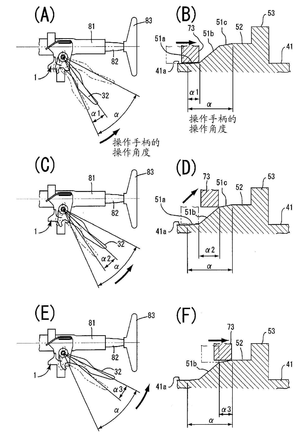
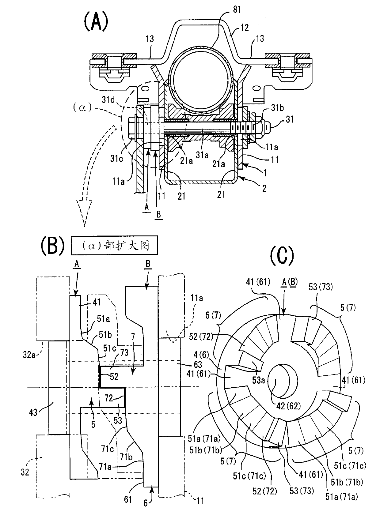
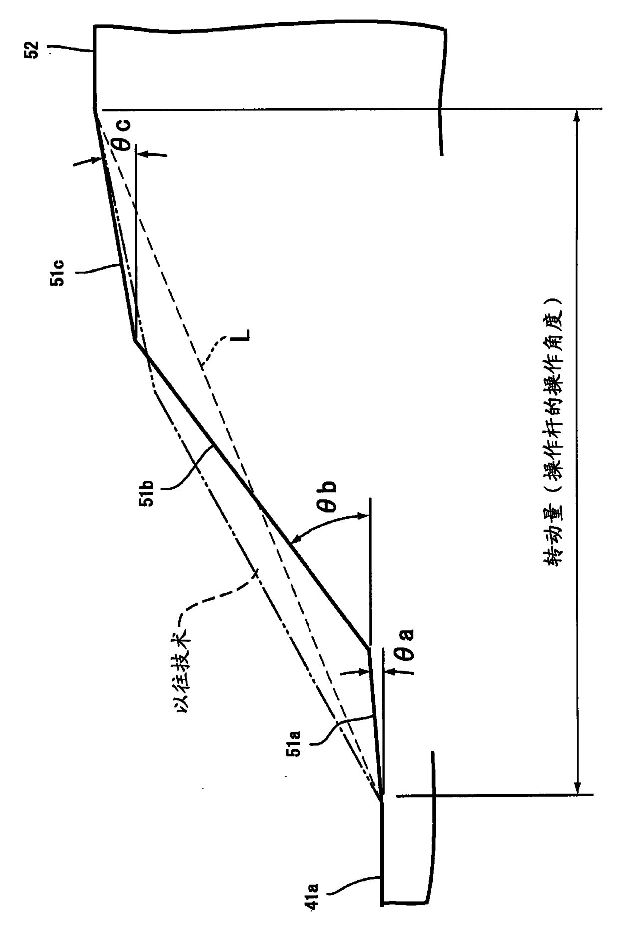
[0026] Embodiments of the present invention will be described below with reference to the drawings. The present invention is a steering wheel device with the function of tilt adjustment (sometimes also provided with telescopic adjustment), mainly composed of a fixed bracket 1, a movable bracket 2, a clamping part 3, a driving cam A, and a driven cam B [refer to figure 1 (A)].

[0027] Furthermore, the movable bracket 2 integrally formed with the steering column 81 is supported on the fixed bracket 1 so as to be tilt-adjustable. In this tilt adjustment, the locking (clamping) and unlocking (clamping release) of the movable bracket 2 to the fixed bracket 1 are approached by the operation of the driving cam A and the driven cam B accompanied by the operation of the clamp 3 . and leave to carry out [cf. figure 1 (A), figure 1 (B)].

[0028] The fixed bracket 1 is formed by fixed side parts 11 , 11 , a connecting part 12 , and mounting parts 13 , 13 . The fixed side portion 1...


PUM


Abstract

A steering apparatus of the present invention includes a fixed bracket (1), a fastener (3), a primary cam (A) that rotates with a rotation operation of the fastener, and a secondary cam (B) that is non-rotatably attached to a fixed side portion and is in contact with the primary cam. Cam operating portions each including an inclined surface portion (51,71), a high level surface (52,72), and a contact protrusion are formed at regular intervals along a circumferential direction on a base flat surface of each of the primary cam and the secondary cam, and the inclined surface portion is constituted by a low gradually inclined surface (51a, 71a), a middle sharply inclined surface (51b, 71b), and a high gradually inclined surface (52,72) arranged in this order from the base flat surface toward the high level surface. With the arrangement, operability of an operating lever in locking and unlocking is improved.

Description

technical field [0001] The present invention relates to a steering wheel device capable of improving the operability of a control lever at the time of locking and unlocking. Background technique [0002] Conventionally, various steering wheel devices having tilt / telescopic functions have been developed. In particular, Patent Document 1 (JP-A-2002-59851) discloses a steering wheel device having a cam mechanism. The specific contents of Patent Document 1 are as follows. On the opposing surface 22 a of the cam 22 with respect to the cam follower 21 , a pair of cams for releasing the lock are provided so as to face each other across the central axis of the cam 22 (the central axis C of the support shaft 15 ). The first positioning part 26 for positioning the cam follower 21, and the second positioning part 27 for positioning the cam follower 21 at the time of locking [refer to Patent Document 1]. image 3 (a)]. [0003] Between the first and second positioning parts 26 and 27...

Claims


Application Information

Patent Timeline
Patent Type & Authority Applications(China)
IPC IPC(8): B62D1/18
CPCB62D1/184
Inventor 广冈幸治杉下杰
Owner YAMADA SEISAKUSHO KK
Why Eureka
Try Eureka