A fuel injector disassembly test bench

A fuel injector and test bench technology, which is used in the testing of fuel injection devices, machinery/structural components, instruments, etc., can solve the problems of low efficiency of disassembly and assembly, high price, and inability to perform in one step, and achieve station positioning. Fast and accurate, low manufacturing cost, convenient and reliable operation

Active Publication Date: 2019-05-14
SOUTH CHINA UNIV OF TECH
View PDF7 Cites 0 Cited by
  • Summary
  • Abstract
  • Description
  • Claims
  • Application Information

AI Technical Summary

Problems solved by technology

Electronically controlled fuel injectors are precision parts, and the test bench requirements for assembly and disassembly are relatively high, which makes the structure of the test bench complex and expensive
[0003] At present, the disassembly and assembly tables used in most maintenance stations need to be clamped multiple times, and the disassembly and assembly are completed in multiple processes. Clamping can easily cause fuel injector wear, thereby reducing assembly accuracy, and the efficiency of disassembly and assembly is also very low
There are also some repair stations that use rotatable fuel injector disassembly and assembly test benches. For example, Patent Application No. 201210571276.6 discloses a fuel injector disassembly and assembly test bench. During the process of disassembly or assembly, the force will cause rotation, which will affect the normal work. Therefore, it is necessary to set limit clamps and auxiliary fixing rods for both ends of the injector. Therefore, this structure cannot be in place in one step when the station is rotated, and it needs to be rotated Then fix the ends of different injectors with limit fixtures and auxiliary fixing rods, resulting in relatively many parts of the entire test bench. The operation process is cumbersome. In addition, there are slow rotation speeds, high lubrication requirements, and easy jamming lack of

Method used


Image

  • A fuel injector disassembly test bench
  • A fuel injector disassembly test bench

Examples


Embodiment 1

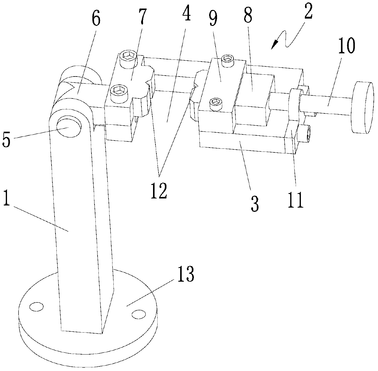
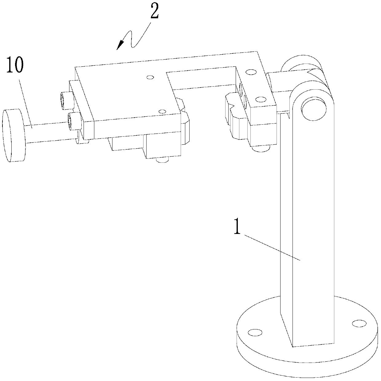
[0024] A fuel injector disassembly test bench, comprising a pillar 1, a turning arm 2 connected to the pillar and capable of turning over relative to the pillar, the turning arm has a fuel injector for clamping the fuel injector fixture.

[0025] Preferably, the turning arm includes a disassembly platform 3, one end of the disassembly platform is hinged on the pillar, and a jaw 4 is opened on the disassembly platform, and the fuel injector fixture is arranged on the jaw.

[0026] Preferably, a turning hinge shaft 5 is also provided, and the turning hinge shaft passes through the top of the pillar and one end of the dismounting platform to hinge the disassembling platform on the top of the pillar.

[0027] Preferably, the top of the pillar is provided with a hinged groove, and through holes are provided on the two side walls of the hinged groove, and a cantilever 6 protrudes from one end of the dismounting platform, and a hinged hole is provided on the cantilever, and the turni...


PUM


Abstract

The invention discloses an oil sprayer dismounting and assembling test stand which comprises a supporting column and a turnover arm. The turnover arm is hinged to the supporting column and can turn over relative to the supporting column. An oil sprayer clamp for clamping an oil sprayer is arranged on the turnover arm. When the oil sprayer dismounting and assembling test stand is used for dismounting and assembling the two ends of the oil sprayer, a cantilever of the dismounting and assembling test stand is located at a lower limit position, that is, the cantilever is in contact with the bottom of a hinge groove, therefore, in the dismounting and assembling process, even though downward pressure, forward pressure, backward pressure, leftward pressure and rightward pressure are generated, the turnover arm cannot swing or move relative to the supporting column, that is, the turnover arm can turn over when bearing upward force and cannot move when bearing force in the other directions, it is guaranteed that the dismounting and assembling process can be carried out stably, and a fixing device does not need to be arranged so that the situation that movement is generated to influence dismounting and assembling can be avoided.

Description

technical field [0001] The invention relates to a disassembly and assembly test bench, in particular to a fuel injector disassembly and assembly test bench. Background technique [0002] The fuel injector is an important part of the engine fuel supply system. It is frequently used, and it is easy to wear and block the fuel injector. It is a major part of automobile maintenance. Electronically controlled fuel injectors are now used in the mainstream market. Electronically controlled fuel injectors are precision parts, and the test bench requirements for assembly and disassembly are relatively high, which makes the structure of the test bench complex and expensive. [0003] At present, the disassembly and assembly tables used in most maintenance stations need to be clamped multiple times, and the disassembly and assembly are completed in multiple processes. Clamping is easy to cause wear of the injector, thereby reducing the assembly accuracy, and the efficiency of disassemb...

Claims


Application Information

Patent Timeline
Patent Type & Authority Patents(China)
IPC IPC(8): F02M65/00
Inventor 张勇郭大庆
Owner SOUTH CHINA UNIV OF TECH
Why Eureka
Try Eureka