Automatic-water-squeezing mop convenient to use

A self-squeezing water and mop technology, applied in applications, household appliances, carpet cleaning, etc., can solve the problems of inconvenient operation, slow automatic turning and returning of the mop head, affecting work efficiency, etc., to achieve labor-saving operation and convenient water-squeezing operation Effect

Active Publication Date: 2018-01-09
浙江爱格家居用品有限公司
View PDF7 Cites 3 Cited by
  • Summary
  • Abstract
  • Description
  • Claims
  • Application Information

AI Technical Summary

Problems solved by technology

However, under this structure, when the mop head needs to be rotated to a position where the angle between the mop head and the mop rod is less than 30°, the automatic flipping and homing can be real

Method used


Image

  • Automatic-water-squeezing mop convenient to use
  • Automatic-water-squeezing mop convenient to use
  • Automatic-water-squeezing mop convenient to use

Examples


Embodiment 1

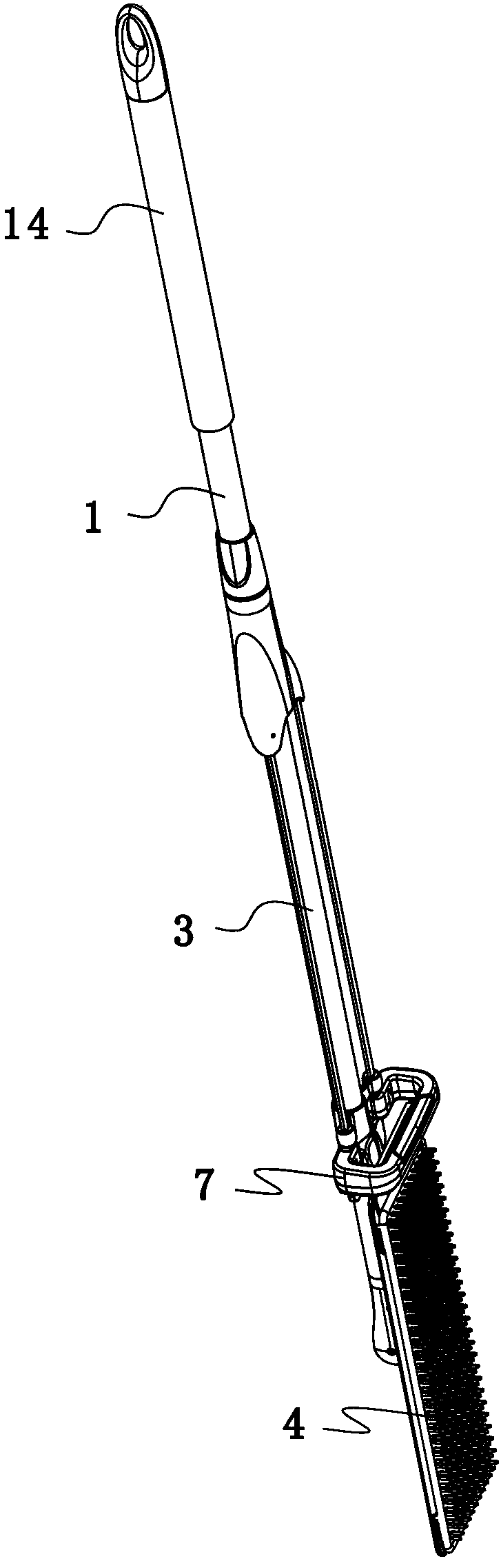
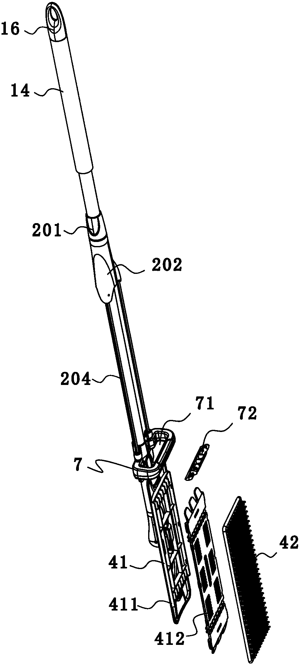
[0042] Such as Figure 17-7 , Shown in 14-22, a kind of self-squeezing water mop comprises a mop head 4, a rolling cover structure and a mop rod, and the rolling cover structure includes a rolling cover 7, which is provided with a perforation 71 for the mop head to pass through The mop rod includes a second rod part 1 and a first rod part 3, the second rod part 1 is movably sleeved outside the first rod part 3, and the second rod part 1 can reciprocate up and down along the first rod part 3 Sliding, the stroke sleeve 7 is connected with the second rod 1, and can move up and down under the drive of the second rod 1; the upper end of the second rod 1 is covered with a soft cover 14, which makes it more comfortable to hold this part; The lower end of the first rod part 3 is movably connected with the mop head 4, and then the mop head 4 can be rotated to a position parallel to the mop rod, and penetrates into the through-hole 71 when the stroke sleeve 7 moves up and down. Further...

Embodiment 2

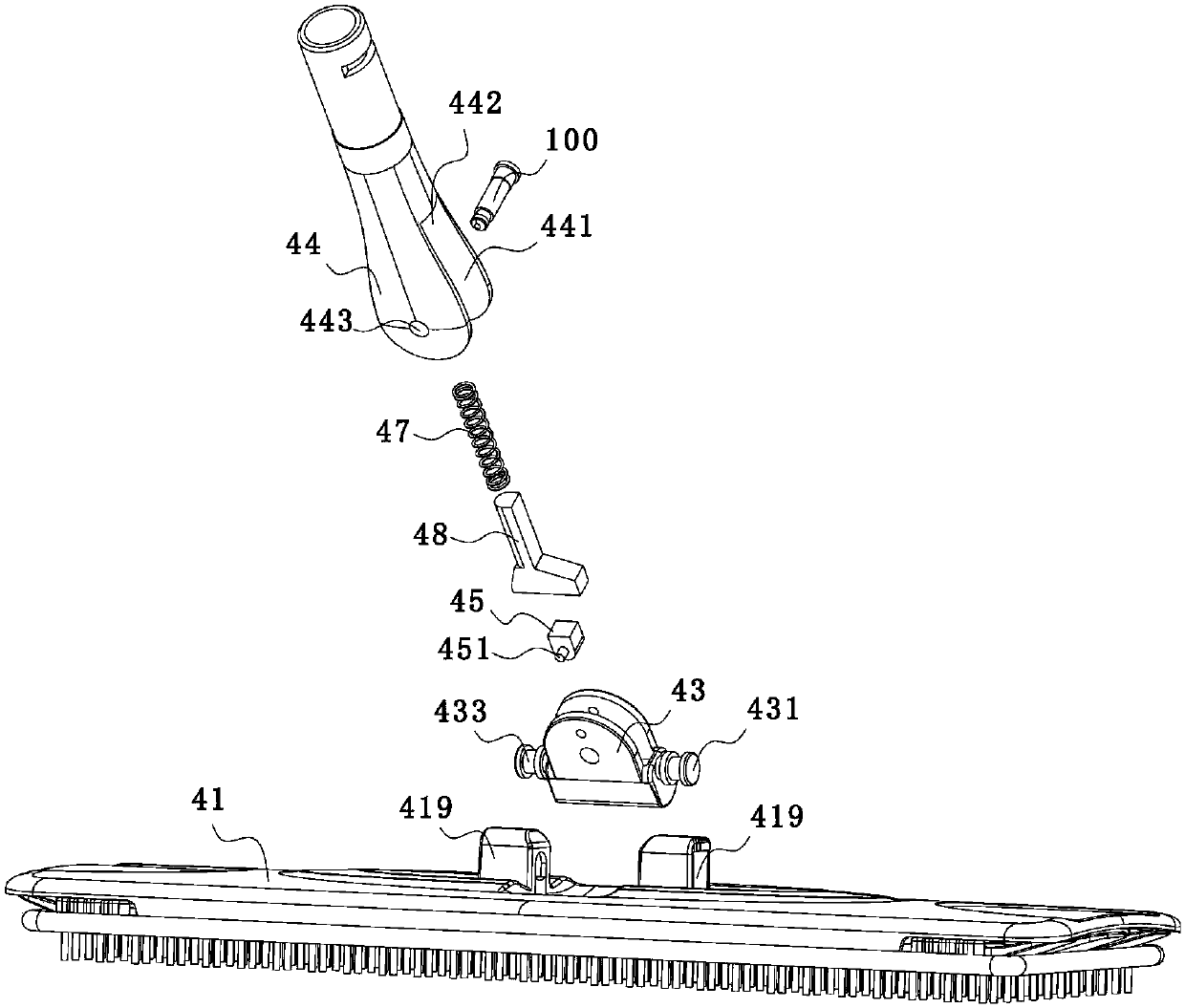
[0062] Such as Figure 8-11 As shown, the difference between this embodiment and Embodiment 1 is that the contact surface of the adjustment member and the push member is an arc surface, and preferably, the adjustment member is a roller; we set the sliding surface 481 The first positioning part 482 and the second positioning part 483, when the mop is in the state of mopping the floor, the adjustment part 45 cooperates with the first positioning part 482; when the mop is in the cleaning state, the adjustment part 45 and the The second positioning part 483 cooperates, so that the positioning of the mop rod is more firm; specifically, the second positioning part 483 is an arc-shaped slot provided at the lower part of the push piece 45, and the first positioning part 482 is an inclined plane located at the lower end of the push member 45; when the mop rod 5 is perpendicular to the mop head 4, the adjusting member 45 snaps into the first positioning portion 482, thereby effectively ...

Embodiment 3

[0064] Such as Figure 12-14 As shown, the difference between this embodiment and Embodiment 1 is that the connecting member 44 is provided with a positioning structure, the positioning structure includes a moving part 491 and a positioning convex portion 492, and the positioning convex portion 492 is arranged on one of the connecting portions Above; the moving part 491 is a moving block 492 placed in the through cavity and a connecting rod 493 pierced in the moving block, the two ends of the connecting rod protrude to the outer surface of the moving block, and the connecting The part 44 is provided with a hole for the connecting rod to penetrate, so as to realize the fixed connection between the connecting rod 493 and the connecting part 44, so that the moving block 492 is effectively limited in the through cavity of the connecting part; the lower end of the moving part 492 is connected with a Spring 494, the upper end of the moving part stretches out to the through cavity, a...


PUM


Abstract

The invention discloses an automatic-water-squeezing mop convenient to use. The automatic-water-squeezing mop convenient to use comprises a mop rod, a mop head movably matched with the mop head and astroking cover, the stroking cover is provided with a penetrating opening, and the mop head can be turn over to the position parallel to the mop rod and penetrate into the penetrating opening; the mophead comprises a mop plate and an adjusting base movably connected with the mop plate; a connecting part is arranged at the lower end of the mop rod, and is movably connected with the adjusting base;an adjusting part is movably connected to the adjusting base, the connecting part is provided with a pushing part and an elastic part matched with the pushing part, and a slide face matched with theadjusting part is formed in the pushing part. Through the cooperation of the adjusting part and the pushing part, the purpose that the mop head is rotated for a certain angle relative to the mop rod and then quickly turned over to the position parallel to the mop rod can be achieved, thus the mop head does not need to be manually wrenched to be turned over, the operation saves labor, and the water-squeezing operation is more convenient.

Description

technical field [0001] The invention belongs to the technical field, in particular to an easy-to-use self-squeezing water mop. Background technique [0002] Chinese patent CN206063099 discloses "A Mop Head Automatic Homing Mechanism", which includes a connecting rod, a mop head, an opening on the mop head, a first movable pin, a second movable pin and a connecting part, and when the mop head is overturned During the process, the automatic homing of the mop head is realized through the cooperation of the first movable pin, the second movable pin and the connecting part, that is, the mop head is rotated to a position parallel to the mop rod. However, under this structure, when the mop head needs to be rotated to a position where the angle between the mop head and the mop rod is less than 30°, the automatic flipping and homing can be realized. Basically, it is necessary to manually assist the mop head to turn over, which is inconvenient to operate; The speed of automatic flip ...

Claims


Application Information

Patent Timeline
IPC IPC(8): A47L13/256A47L13/258A47L13/59
Inventor 苏文康
Owner 浙江爱格家居用品有限公司
Why Eureka
Try Eureka