Air blowing fan, circulator, micro-particle diffusion device, and air circulation method

A circulator and fan technology, which is applied in the field of particle diffusion devices, can solve the problems of poor air supply efficiency and increased noise.

Inactive Publication Date: 2012-10-24
SHARP KK
View PDF3 Cites 9 Cited by
  • Summary
  • Abstract
  • Description
  • Claims
  • Application Information

AI Technical Summary

Problems solved by technology

But in this case, since the air flow is also sharply turned on the exhaust side of the fan, the air supply efficiency becomes poor and the noise becomes louder
[0020] In addition, the same problem exists in the particle diffusion device that sends particles into the room and diffuses the particles. In this particle diffusion device, a particle generating device is installed in the air flow passage of the circulator, and the particle generating device generates ions, fragrances, deodorants, etc. , insecticides, fungicides and other particles

Method used


Image

  • Air blowing fan, circulator, micro-particle diffusion device, and air circulation method
  • Air blowing fan, circulator, micro-particle diffusion device, and air circulation method
  • Air blowing fan, circulator, micro-particle diffusion device, and air circulation method

Examples


Embodiment Construction

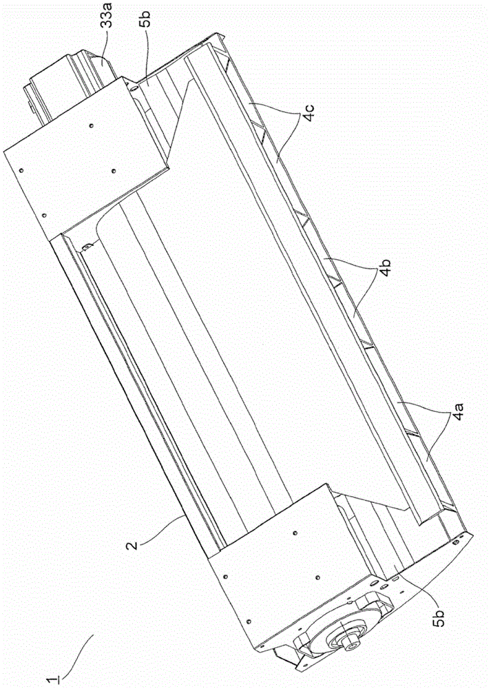
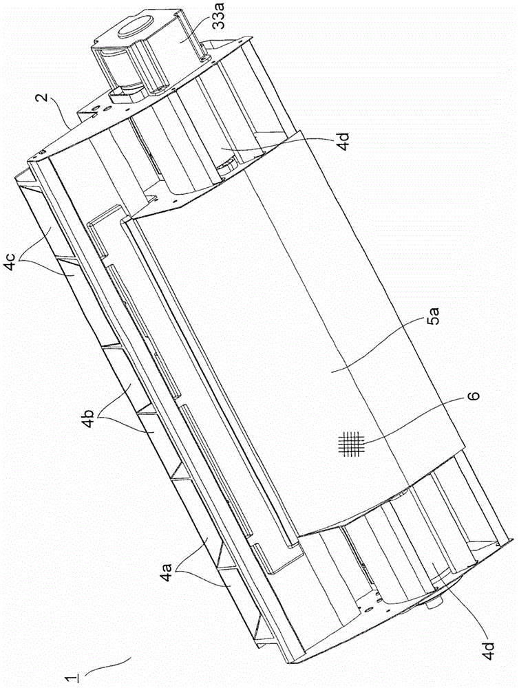
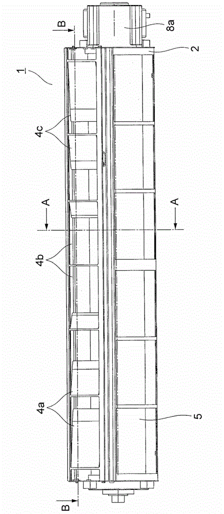
[0143] Embodiments of the present invention will be described below with reference to the drawings. figure 1 , figure 2 and image 3 It is a perspective view viewed from above, a perspective view viewed from below, and a front view of the microparticle diffusion device according to the first embodiment. The particle diffusion device 1 is covered by the box body 2, and is arranged on a side wall S and a top wall T of the chamber (refer to Figure 4 ) near the corner of the house. The box body 2 can be installed on the side wall S, or the box body 2 can be installed on the top wall T near the side wall S.

[0144] A suction port 5 is opened on the lower surface of the box body 2 . A filter 6 is arranged on the suction port 5 . On the top of the front surface of the housing 2, a first outlet 4a, a second outlet 4b, and a third outlet 4c are sequentially arranged horizontally from the right side toward the room. The first outlet 4a, the second outlet 4b and the third outlet...


PUM


Abstract

A circulator (1) which is mounted on a side wall (S) in a room or on a ceiling wall (T) located close to the side wall (S) in a room and which circulates air present in the room. The circulator (1) comprises, in order from a first wall surface (P1) adjacent to the side wall (S) in the horizontal direction, a first outlet (4a), a second outlet (4b), and a third outlet (4c) which are disposed next to each other in the horizontal direction. A first air flow (A1) which flows along the ceiling wall (T) and descends along the first wall surface (P1) is delivered from the first outlet (4a), a second air flow (A2) which flows along the ceiling wall (T) and descends along a second wall surface (P2) facing the side wall (S) is delivered from the second outlet (4b), and a third air flow (A3) which flows along the ceiling wall (T) and descends along a third wall surface (P3) facing the first wall surface (P1) is delivered from the third outlet (4c)

Description

technical field [0001] The invention relates to a fan for sending out airflow. Furthermore, the present invention relates to a circulator and an air circulation method for circulating indoor air. Furthermore, the present invention relates to a particle diffusion device for sending out particles such as ions and diffusing them into a chamber. Background technique [0002] Patent Document 1 discloses a conventional circulator. The circulator is installed on the indoor floor, has a suction port on the lower part, and has a blowing port on the upper surface. Driven by the fan installed inside the circulator, the air in the room is sucked in from the suction port along the floor, and the air is sent forward and upward from the blower port. Thereby, indoor air can be circulated. [0003] In addition, Patent Document 2 discloses a conventional particle diffusion device. The microparticle diffuser is arranged on the top surface of the refrigerator or the like, and a fan is inst...

Claims


Application Information

Patent Timeline
Patent Type & Authority Applications(China)
IPC IPC(8): F24F7/007F24F7/00F24F13/06F24F1/0073F24F1/0076
CPCF24F2001/0096F24F7/007F24F7/065F24F1/0071F24F1/0073F24F1/0076
Inventor 高桥雅也大塚雅生竹田康坚
Owner SHARP KK
Why Eureka
Try Eureka