Air conditioner

An air conditioning and air conditioning technology, applied in the field of air conditioning devices, can solve the problems of inability to eliminate the danger of refrigerants, high price, poor construction, etc., and achieve the effect of environmental protection of the earth

Active Publication Date: 2012-11-07
MITSUBISHI ELECTRIC CORP
View PDF18 Cites 4 Cited by
  • Summary
  • Abstract
  • Description
  • Claims
  • Application Information

AI Technical Summary

Problems solved by technology

[0014] In the air conditioner described in Patent Document 2, in order to select cooling or heating for each indoor unit, it is necessary to connect four pipes from the outdoor side to the room, resulting in poor workability.
In the air-conditioning device described in Patent Document 3, the indoor units need to have a secondary medium circulation mechanism such as a pump, so the system is not only expensive, but also noisy, which is not practical.
Moreover, since the heat exchanger is located near the indoor unit, the risk of refrigerant leaking close to the room cannot be eliminated, and flammable refrigerants cannot be used.
[0015] In the air-conditioning apparatus described in Patent Document 4, since the primary refrigerant after heat exchange flows into the same flow path as the primary refrigerant before heat exchange, when a plurality of indoor units are connected, it cannot pass through each indoor unit. machine to its maximum capacity and become a structure that wastes energy
In addition, regarding the connection of the branch unit and the extension pipe, two pipes are required for cooling, and two pipes are required for heating, making a total of four pipes. As a result, the structure is similar to a system in which the outdoor unit and the branch unit are connected by four pipes. become a poorly constructible system

Method used


Image

  • Air conditioner
  • Air conditioner
  • Air conditioner

Examples


Embodiment Construction

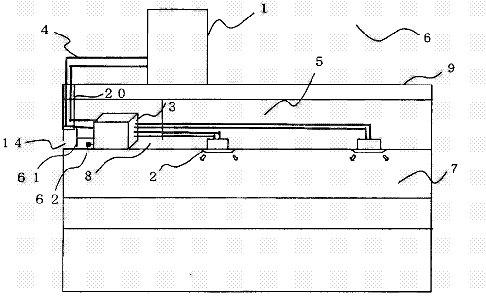
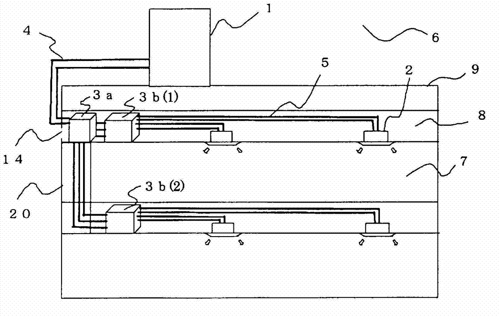
[0030] Embodiments of the present invention will be described based on the drawings. figure 1 and figure 2 It is a schematic diagram which shows the installation example of the air-conditioning apparatus which concerns on embodiment of this invention. based on figure 1 and figure 2 An example of installation of an air conditioner will be described. This air conditioner utilizes a refrigeration cycle (refrigerant circuit A, heat medium circuit B) that circulates a refrigerant (heat source side refrigerant, heat medium), and each indoor unit can freely select a cooling mode or a heating mode as an operation mode. model. Additionally, include figure 1 In addition, in the following drawings, the relationship of the size of each component may differ from the actual situation.

[0031] exist figure 1 Among them, the air conditioner of this embodiment includes one outdoor unit 1 as a heat source unit, a plurality of indoor units 2 , and a heat medium relay unit 3 interposed ...


PUM


Abstract

Provided is an air conditioner wherein it is possible to conserve energy and to ensure safety with regard to the refrigerant. Disclosed is an air conditioner equipped with: a heat medium exchanger (3) disposed within a space (8) in a building (9), which is different from the space in which the air is conditioned, and provided with inter-heat medium heat exchangers (15a, 15b) which exchange the heat between a flammable refrigerant and a heat medium that is different from the refrigerant, and a housing (50) which houses the inter-heat medium heat exchangers (15a, 15b), and has an air vent (24) that allows air to flow through the housing space and the outside of the housing space; one or more outdoor units (1) which circulate the refrigerant by being connected to the heat medium exchanger (3) via a pipe, and which are disposed on the outside of the building (9) or an outdoor space (6) within the building (9), which leads to the outside of the building (9); and one or more indoor units (2) which are connected to the heat medium exchanger (3) via a pipe by means of a different system from the outdoor units (1), and which are provided with a use-side heat exchanger (26) which exchanges the heat between the heat medium and the air in the indoor space (6) by circulating the heat medium.

Description

technical field [0001] The present invention relates to an air conditioner suitable for use in, for example, a multi-unit air conditioner for a building. Background technique [0002] Conventionally, in an air-conditioning apparatus such as a multi-air conditioner for a building, a cooling operation or a heating operation is performed by, for example, circulating a refrigerant between an outdoor unit, which is a heat source unit disposed outdoors, and an indoor unit disposed indoors. Specifically, the air-conditioned space is cooled or heated by the air heated by the heat dissipation of the refrigerant or the cooled air by the heat absorbed by the refrigerant. As refrigerants used in such air-conditioning devices, for example, HFC (hydrofluorocarbon) refrigerants are often used, and carbon dioxide (CO2) has also been proposed. 2 ) and other natural refrigerants. Here, non-flammable refrigerants are used. [0003] On the other hand, there are air-conditioning apparatuses o...

Claims


Application Information

Patent Timeline
Patent Type & Authority Applications(China)
IPC IPC(8): F24F5/00F24F11/02
CPCF25B49/005F24F2011/0084F25B25/005F24F3/06F25B2400/12F25B13/00F25B2500/222F25B2313/0231F24F11/36
Inventor 山下浩司森本裕之
Owner MITSUBISHI ELECTRIC CORP
Why Eureka
Try Eureka