Method, apparatus and computer program for selecting a stereoscopic imaging viewpoint pair

A technology of stereoscopic imaging and viewpoint, applied in computing, stereoscopic system, stereophotography, etc., to achieve the effect of effective use and reduced display

Active Publication Date: 2012-12-19
NOKIA TECH OY
View PDF3 Cites 6 Cited by
  • Summary
  • Abstract
  • Description
  • Claims
  • Application Information

AI Technical Summary

Problems solved by technology

Thus there are compatibility issues when viewing stereoscopic images on a different display than the one intended

Method used


Image

  • Method, apparatus and computer program for selecting a stereoscopic imaging viewpoint pair
  • Method, apparatus and computer program for selecting a stereoscopic imaging viewpoint pair
  • Method, apparatus and computer program for selecting a stereoscopic imaging viewpoint pair

Examples


Embodiment Construction

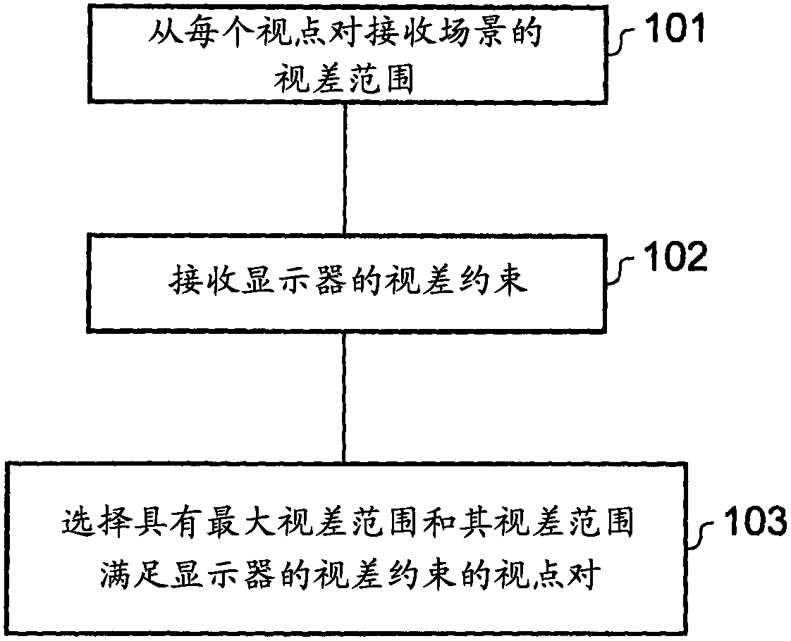
[0039] The figures illustrate a method comprising: receiving (101) a hint of a disparity range of an object scene from each of two or more pairs of stereoscopic imaging viewpoints; receiving (102) a hint of a disparity constraint of a stereoscopic display; and Selecting (103) a pair of stereoscopic imaging viewpoints whose disparity range is the largest and whose disparity range satisfies the disparity constraint of the stereoscopic display.

[0040] illustrate

[0041] figure 1 A flowchart illustrating a method according to various embodiments of the invention. In block 101 , a process of receiving cues for a disparity range of an object scene from each of two or more pairs of stereoscopic imaging viewpoints is performed. In block 102, a process of receiving a hint of a disparity constraint for a stereoscopic display is performed. Finally, in block diagram 103, a process of selecting a stereoscopic imaging viewpoint pair whose parallax range is the largest and whose para...


PUM


Abstract

A method (100), an apparatus (200) and a computer program (204) for receiving an indication of a disparity range (SIVP1 D, SIVP2D) of an object scene from each of two or more stereoscopic imaging viewpoint pairs (SIVPi, SIVP2); receiving an indication of a disparity constraint (SDD) of a stereoscopic display (903); and selecting a stereoscopic imaging viewpoint pair whose disparity range is the largest and whose disparity range satisfies the disparity constraint of the stereoscopic display.

Description

technical field [0001] Embodiments of the present invention relate to methods, apparatuses, computer programs and computer readable storage media. In particular, the embodiments relate to methods, apparatus, computer programs and computer readable storage media in the field of stereoscopic imaging. Background technique [0002] Current stereoscopic systems use a pair of cameras with a fixed separation distance, typically designed to acquire images by each camera. A stereoscopic image is generated from the two images for display on a specific stereoscopic display. Such systems are limited to acquiring stereoscopic images of predetermined scene environments for display on predetermined displays. Thus there is a compatibility problem when viewing stereoscopic images with a display other than the intended display. Contents of the invention [0003] According to various, but not necessarily all, embodiments of the present invention, there is provided a method for receiving, ...

Claims


Application Information

Patent Timeline
Patent Type & Authority Applications(China)
IPC IPC(8): H04N13/00G03B35/08G06T7/00H04N13/30G03B30/00
CPCH04N13/0242H04N13/04H04N13/0239H04N13/0022H04N13/0066H04N13/0203G03B35/08H04N13/0497H04N13/243H04N13/189H04N13/204H04N13/239H04N13/128H04N13/178H04N13/398H04N13/30H04N13/00G06T7/00
Inventor L·波科特
Owner NOKIA TECH OY
Why Eureka
Try Eureka