Controlled-silicon adapting LED (light-emitting diode) driving circuit, method and switch power supply

A technology of LED driving and switching power supply, which is applied in the direction of electric light source, electroluminescence light source, electric lamp circuit layout, etc., which can solve the problems of noise emission, oscillation, and different brightness of LED lamp load, and achieve the effect of avoiding flicker and noise

Active Publication Date: 2014-06-25
SILERGY SEMICON TECH (HANGZHOU) CO LTD
View PDF5 Cites 1 Cited by
  • Summary
  • Abstract
  • Description
  • Claims
  • Application Information

AI Technical Summary

Problems solved by technology

[0003] The LED driving circuit with thyristor in the prior art generally controls the switching action of the power switch tube in the power stage circuit to provide a constant output current for the LED lamp load, and its driving circuit is often equipped with a power factor correction function. Therefore, the input voltage and input current waveforms of its power stage circuit remain consistent, such as figure 1 Shown is the input voltage and input current waveform diagram of the LED drive circuit with thyristor in the prior art. In the LED drive circuit with thyristor in the prior art, the shutdown of the thyristor is generally When the input current of the power stage circuit is less than the holding current of the thyristor, the thyristor is naturally turned off. At this time, since the input voltage has not dropped to zero, the thyristor trigger circuit will be charged to turn on the thyristor again. At this time, the input current may generate as figure 1 The oscillation shown in the figure then causes multiple irregular restarts of the thyristor, which makes the power absorbed by the LED drive circuit from the input side different in each cycle, resulting in different brightness of the LED lamp load in different cycles , causing the LED to strobe and possibly noisy

Method used


Image

  • Controlled-silicon adapting LED (light-emitting diode) driving circuit, method and switch power supply
  • Controlled-silicon adapting LED (light-emitting diode) driving circuit, method and switch power supply
  • Controlled-silicon adapting LED (light-emitting diode) driving circuit, method and switch power supply

Examples


Embodiment Construction

[0033] Several preferred embodiments of the present invention will be described in detail below with reference to the accompanying drawings, but the present invention is not limited to these embodiments. The present invention covers any alternatives, modifications, equivalent methods and schemes made on the spirit and scope of the present invention. In order to provide the public with a thorough understanding of the present invention, specific details are set forth in the following preferred embodiments of the present invention, but those skilled in the art can fully understand the present invention without the description of these details.

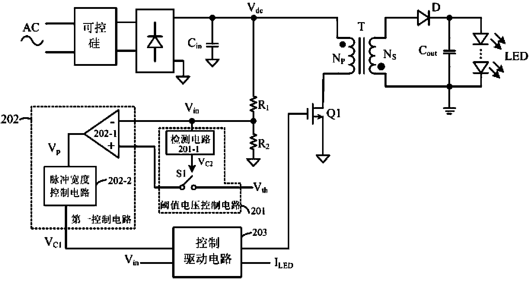
[0034] Referring to Fig. 2, it shows a circuit diagram of an LED driving circuit adapted to a silicon controlled rectifier according to the present invention. The LED driving circuit of the present invention is applied in a switching power supply, by controlling the power switching tube in the switching power supply The switch acts to con...


PUM


Abstract

Disclosed are light-emitting diode (LED) driver circuits, methods, and a switch mode power supply. In one embodiment, an LED driver can include: (i) a silicon-controlled rectifier (SCR) and a rectifier bridge configured to receive an AC voltage, and to generate a phase-loss half sine wave voltage signal; (ii) a threshold voltage control circuit configured to receive a threshold voltage and an input voltage signal that represents the phase-loss half sine wave voltage signal, and to determine whether to output the threshold voltage based on angle information of the input voltage signal; (iii) a first control circuit configured to compare the input voltage signal against the threshold voltage output by the threshold voltage control circuit, and to generate a first control signal; and (iv) a power switch controllable by the first control signal to be off until an absolute value of the AC voltage is reduced to zero.

Description

technical field [0001] The invention relates to the field of switching power supply, more specifically, relates to an LED driving circuit adapted to a thyristor, a driving method and a switching power supply using the same. Background technique [0002] Light-emitting diodes (LEDs) are widely used in offices and homes due to their high efficiency and energy-saving advantages. Today, LED lighting has become the mainstream technology in the field of lighting. However, in the process of replacing existing incandescent lighting with LED lighting, how to It is a key problem that needs to be solved urgently to match the LED lamp well with the thyristor dimmer in the traditional circuit to realize precise dimming. [0003] The LED driving circuit with thyristor in the prior art generally controls the switching action of the power switch tube in the power stage circuit to provide a constant output current for the LED lamp load, and its driving circuit is often equipped with a power ...

Claims


Application Information

Patent Timeline
Patent Type & Authority Patents(China)
IPC IPC(8): H02M3/335H05B37/02H05B44/00
CPCH05B33/0815Y02B20/346H05B33/0851Y02B20/348H05B45/10Y02B20/30H05B45/3725H05B45/385
Inventor 余峰黄晓冬
Owner SILERGY SEMICON TECH (HANGZHOU) CO LTD
Why Eureka
Try Eureka