LED (Light Emitting Diode) control circuit and LED illumination device

A technology for controlling circuits and resistors, applied in lighting devices, lamp circuit layout, electric light sources, etc., can solve problems such as high cost, unfavorable improvement of integration and miniaturization of LED control circuits, and complex circuit structure

Active Publication Date: 2012-12-26
SHENZHEN SUNMOON MICROELECTRONICS
View PDF4 Cites 12 Cited by
  • Summary
  • Abstract
  • Description
  • Claims
  • Application Information

AI Technical Summary

Problems solved by technology

[0003] The purpose of the present invention is to provide an LED control circuit, aiming to solve the problem that the existing LED control circuit has complex circuit structure and high cost, which is not conducive to improving the integration and miniaturization of the LED control circuit.

Method used


Image

  • LED (Light Emitting Diode) control circuit and LED illumination device
  • LED (Light Emitting Diode) control circuit and LED illumination device
  • LED (Light Emitting Diode) control circuit and LED illumination device

Examples


Embodiment Construction

[0014] In order to make the object, technical solution and advantages of the present invention clearer, the present invention will be further described in detail below in conjunction with the accompanying drawings and embodiments. It should be understood that the specific embodiments described here are only used to explain the present invention, not to limit the present invention.

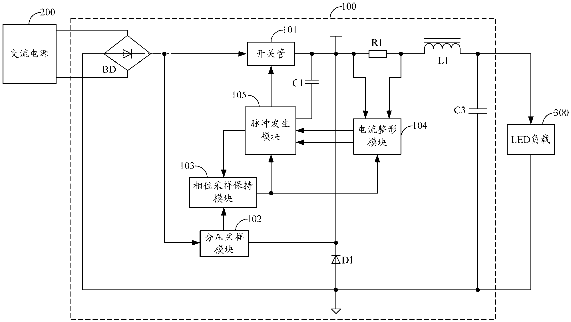
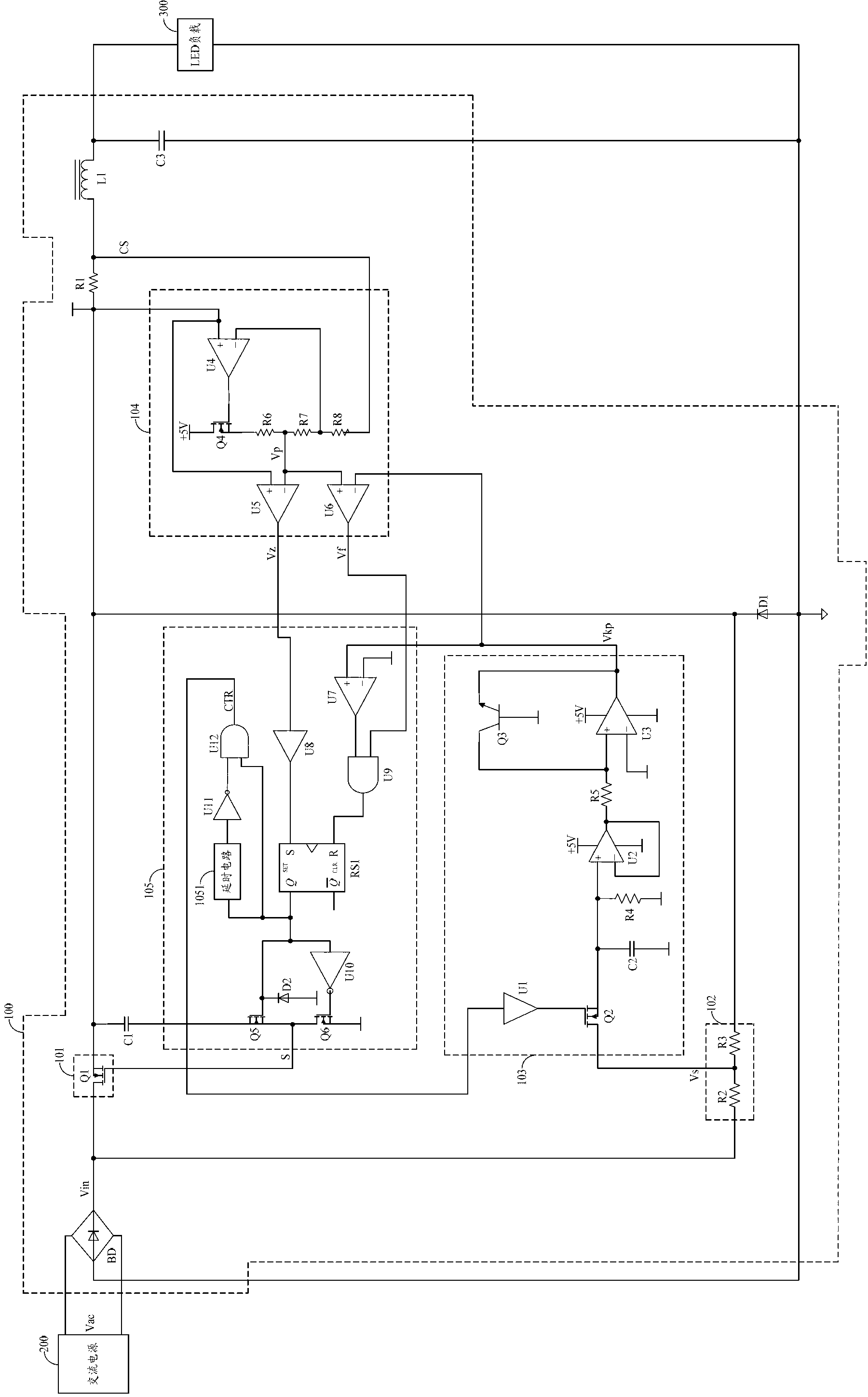
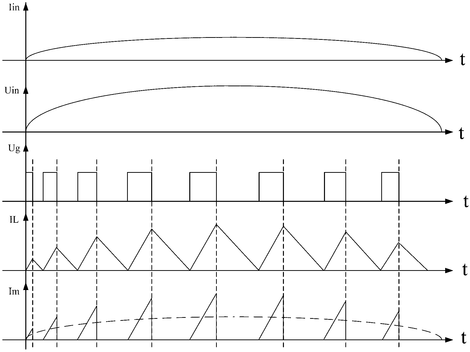
[0015] In the embodiment of the present invention, by using switch tube, capacitor C1, sampling resistor R1, voltage dividing sampling module, diode D1, phase sampling and holding module, current shaping module and pulse generating module in the LED control circuit, the pulse generating module is based on The voltage at the output terminal of the switch tube controls the working state of the voltage-dividing sampling module, and the voltage-dividing sampling module and the current shaping module respectively perform AC voltage in-phase sampling on the output DC of the rectifier bridge and sample the...


PUM


Abstract

The invention belongs to the field of LED (Light Emitting Diode) control, and provides an LED control circuit and an LED illumination device. According to the invention, a switching tube, a capacitor C1, a sampling resistor R1, a voltage division sampling module, a diode D1, a phase sampling and retaining module, a current shaping module and a pulse generation module are adopted in the LED control circuit, wherein the pulse generation module controls the work state of the voltage division sampling module according to the output end voltage of the switching tube; and after the voltage division sample module and the current shaping module respectively perform alternating voltage in-phase sampling on output direct current of a rectifier bridge and sampling on input voltage of a first end of the inductance L1, the phase sampling and retaining module outputs a sampling and retaining voltage signal, and the current shaping module outputs a zero crossing comparison signal and a peak comparison signal to drive the drive pulse generation module to correspondingly output an impulse signal with a specific duty ratio to control the on-off state of the switching tube, so that the circuit is more miniaturized in structure and easy to integrate, the power factor is improved, and constant current driving of the LED load is realized.

Description

technical field [0001] The invention belongs to the field of LED control, in particular to an LED control circuit and an LED lighting device. Background technique [0002] As a new type of light source, LED is widely used in various fields because of its advantages of high brightness, low power consumption and long life. With the development of LED lighting technology, the requirements for LED control circuits are getting higher and higher, such as circuit size, voltage conversion efficiency, power factor and output current, etc., all have strict requirements. Due to the current global leading concept of environmental protection and energy saving, LED control circuits need to be equipped with corresponding power factor correction circuits to meet energy-saving needs. Therefore, in the prior art, a corresponding passive power factor correction circuit is added on the basis of the traditional power conversion circuit to meet the above requirements for the LED control circuit....

Claims


Application Information

Patent Timeline
Patent Type & Authority Applications(China)
IPC IPC(8): H05B37/02
Inventor 郭伟峰林道明李照华赵春波付凌云谢靖
Owner SHENZHEN SUNMOON MICROELECTRONICS
Why Eureka
Try Eureka