Check patentability & draft patents in minutes with Patsnap Eureka AI!

Telescoping operating arm, operating device and injection moulding device

A technology of injection molding and manipulation device, applied in the direction of claw arm, manipulator, manufacturing tool, etc., which can solve the problems of short extension length and contact with each other.

Active Publication Date: 2015-05-06
ENGEL AUSTRIA
View PDF5 Cites 0 Cited by
  • Summary
  • Abstract
  • Description
  • Claims
  • Application Information

AI Technical Summary

Problems solved by technology

[0009] but if Figure 4 As shown in , in the stretched state A there is the following problem: The stretched length Z is rather short, because the guide blocks 5 and 6 will touch each other when moving further along the stretched direction F

Method used


Image

  • Telescoping operating arm, operating device and injection moulding device
  • Telescoping operating arm, operating device and injection moulding device
  • Telescoping operating arm, operating device and injection moulding device

Examples


Embodiment Construction

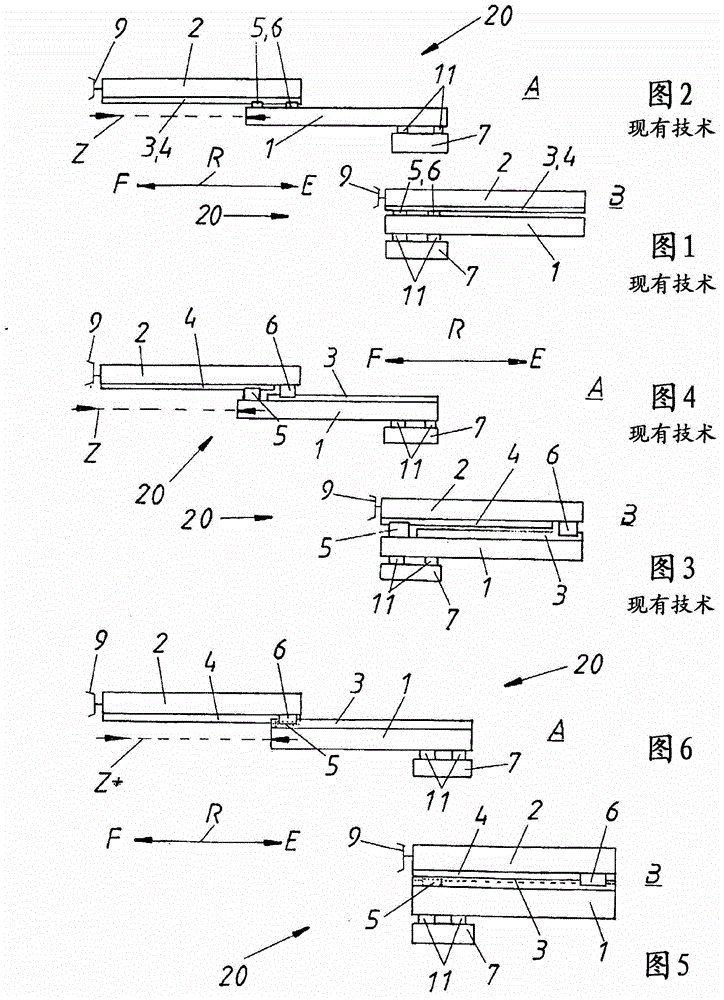
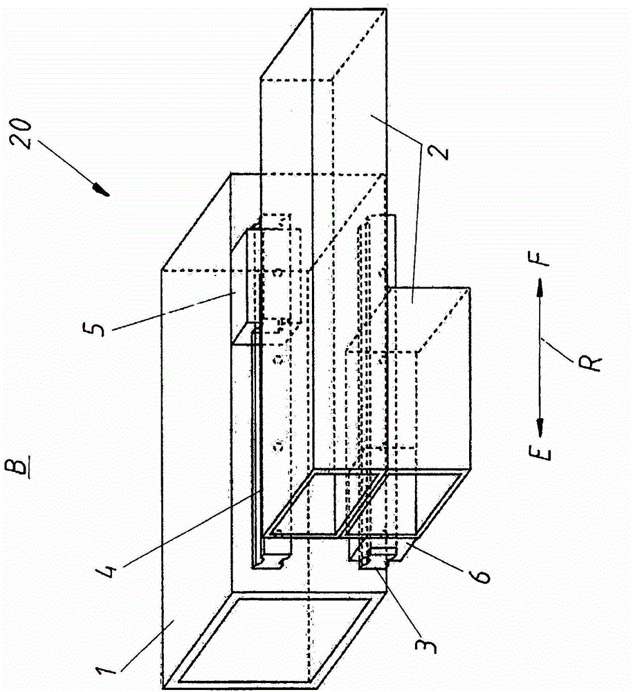
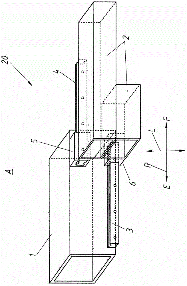
[0025] as already described Figures 1 to 4 On the one hand, the shortcomings existing in the prior art can be Figure 5 Shown to be overcome, the way is: in the shown retracted state B, the second guide block 6 that is arranged at the end of the second branch arm 2 pointing to the retraction direction E and shown in the previous part and The first guide rail 3 , likewise shown in the previous section, corresponds (ie matches) on the first partial arm 1 . On the other hand, the guide block 5 arranged at the end of the first partial arm 1 pointing in the extension direction F is shown in broken lines in the rear part and is connected to the same in the rear part (with broken lines) The second guide rail 4 of the second branch arm 2 is corresponding. Thus, especially compared to the figure 1 and 2 With the known prior art shown in , significantly better stability is obtained even in retracted state B.

[0026] exist Figure 6 A further advantage can be seen in , whereby a ...


PUM


Abstract

The handling arm has two sub-arms (1,2), two parallel guide rails (3,4), and the movable guide jaws (5,6). A sub-arm (1) arranged at the guide jaw (5) is movable by the guide rail (3), and the sub-arm (2) arranged at the guide jaw (6) is movable by the guide rail (4). In the extended position (A) of the sub-arms, the rectangular line of sight of the sub-arm (1) arranged in the guide jaw (5) and the sub-arm (2) arranged on the guide arm (6) is partially or completely obscured in the orientation direction (R) of the guide rails.

Description

technical field [0001] The invention relates to a manipulating arm for a manipulating device of injection molding equipment, which comprises a first branch arm and a second branch arm, and the first branch arm and the second branch arm can pass through at least two mutually parallel guide rails and At least two guide blocks that can travel on the guide rails move, wherein the guide blocks arranged on the first branch arm can travel on the guide rails arranged on the second branch arm, and the guide blocks arranged on the second branch arm can travel on the guide rails arranged on the second branch arm. The block can travel on the guide rail provided on the first branch arm. The invention also relates to a manipulating device equipped with such a manipulating arm, and also to an injection molding machine equipped with such a manipulating device. Background technique [0002] In order to move different parts (mostly in factories), manipulator arms are used in a great variety ...

Claims


Application Information

Patent Timeline
Patent Type & Authority Patents(China)
IPC IPC(8): B29C45/17B29C45/14
CPCB25J18/025B22D17/20
Inventor P·W·蔡泽G·M·胡贝尔
Owner ENGEL AUSTRIA
Features
  • R&D
  • Intellectual Property
  • Life Sciences
  • Materials
  • Tech Scout
  • Unparalleled Data Quality
  • Higher Quality Content
  • 60% Fewer Hallucinations
Learn More