

Optical element with electric field direction parallel to liquid crystal layer
A technology of electric field direction and optical devices, applied in optics, liquid crystal materials, nonlinear optics, etc., can solve problems such as slow response speed and high driving voltage in IPS mode
Active Publication Date: 2013-01-23
JIANGSU HECHENG DISPLAY TECHCO
View PDF4 Cites 3 Cited by
- Summary
- Abstract
- Description
- Claims
- Application Information
AI Technical Summary
Problems solved by technology
[0007] In order to solve the problem of high driving voltage and slow response speed in IPS mode
Method used
View moreImage
Smart ImageViewing Examples


Examples
Embodiment 1
[0057] Add the optically active substance involved in the present invention to the liquid crystal composition M-1 according to the weight percentage listed in Table 3, fill it between the two substrates of the liquid crystal display for performance testing, and the test data are shown in the following table:
[0058] Table 3 liquid crystal composition formula and test performance thereof
[0059]
[0060] The composition has favorable low Δn value, moderately high Δε value, very low rotational viscosity and extremely low driving voltage, which can effectively solve the shortcoming of high driving voltage in IPS display mode. It is therefore ideally suited for use in monitors operating in IPS display mode.
Login to View More PUM
| Property | Measurement | Unit |
|---|---|---|
| thickness | aaaaa | aaaaa |
Abstract
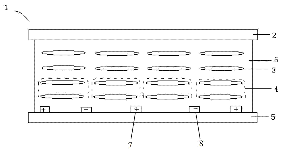
The invention provides an optical element parallel with the electric field direction parallel to a liquid crystal layer. The optical element with the electric field direction parallel to the liquid crystal layer comprises an upper base plate, a lower base plate and the liquid crystal layer, wherein the lower base plate is positioned below the upper base plate, and the liquid crystal layer is positioned between the upper base plate and the lower base plate and comprises a positive or negative liquid crystal medium, and the liquid crystal medium comprises at least one optical activity component. According to the optical element, liquid crystal molecules in an electric field can obtain high power so as to rapidly rotate 90 degrees with low driving voltage, the use requirements of a display on the low driving voltage can be met, and a liquid crystal composition between the upper base plate and the lower base plate has low viscosity and a high clearing point.
Description
technical field [0001] The invention relates to the field of liquid crystal display, in particular to an optical device whose electric field direction is parallel to the liquid crystal layer. At the same time, it relates to a liquid crystal composition applied in an IPS mode, and in particular relates to a liquid crystal medium added with a chiral agent applied in an IPS mode. Background technique [0002] In recent years, researchers have developed different liquid crystal display modes. Among them, the most important liquid crystal display modes are TN (twisted nematic) mode, STN (super twisted nematic) mode, IPS (in-plane switching) mode, OCB (optical controlled birefringence) mode and PDLC (polymerized dispersed liquid crystal) mode etc. All of these modes use an electric field, where the TN (Twisted Nematic), STN (Super Twisted Nematic), and OCB (Optical Controlled Birefringence) electric fields are substantially perpendicular to the substrate, or perpendicular to the...
Claims
Login to View More Application Information
Patent Timeline
 Patent Type & AuthorityApplications(China)
IPC IPC(8): G02F1/1333C09K19/52
CPCC09K2019/0437C09K2019/0466C09K2019/301C09K2019/3019C09K2019/3063C09K2019/3077G02F1/134363G02F1/134372
Inventor宋晓龙陈昭远
OwnerJIANGSU HECHENG DISPLAY TECHCO