Cambered adjustable movable flood control wall

A flood control wall, adjustable technology, applied in dikes, coastline protection, dams, etc., can solve the problems of increased transportation costs, long gate opening time, troublesome sandbag disposal, etc., and achieve the effect of low transportation and production costs and convenient installation

Inactive Publication Date: 2013-02-20
上海东泽环境科技股份有限公司
View PDF6 Cites 3 Cited by
  • Summary
  • Abstract
  • Description
  • Claims
  • Application Information

AI Technical Summary

Problems solved by technology

Although stacking sandbags can have a better waterproof effect, due to the heavy weight of the sandbags, it takes more physical strength and time during the accumulation process. Besides, there are more fillers in the sandbags, plus the physical strength and time required during the accumulation process. Therefore the cost is higher
At the same time, once the sandbags are not stacked tightly enough, it will cause water leakage. In addition, after the flood season, it is also very troublesome to dispose of the used sandbags.
There are also some temporary flood control gates in the existing market, but most of them need to do a lot of civil work before installation, so the installation cycle of the gates increases, and the cost increases, causing problems such as low efficiency, and the existing flood control gates Most of the sealing strips need to be installed separately, causing the gate to open for a long time
There is also a mobile combined flood control wall. When the flood season comes, it must be transported to the original dam for combined installation, and it will be dismantled and transported away after the flood season, so the transportation cost will be increased.

Method used


Image

  • Cambered adjustable movable flood control wall
  • Cambered adjustable movable flood control wall
  • Cambered adjustable movable flood control wall

Examples


Embodiment Construction

[0015] Describe in detail its specific implementation below in conjunction with accompanying drawing:

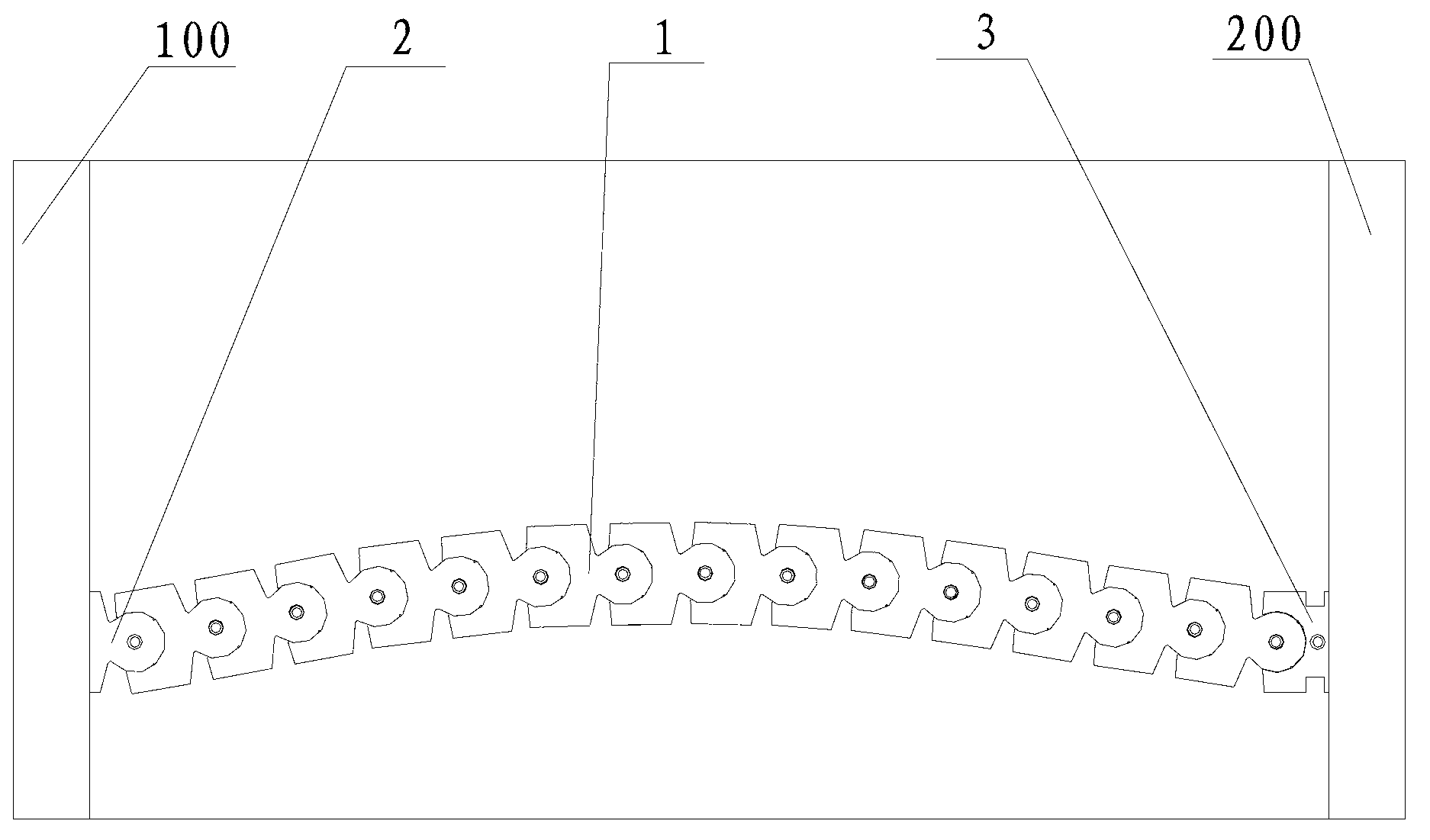
[0016] see Figure 1 to Figure 4 , an arc-shaped adjustable movable flood control wall of the present invention is installed between two building walls 100 and 200, and the movable flood control wall includes a plurality of standard modules 1, a first connecting module 2 and a second connecting module 3, The standard module 1, the first connection module 2 and the second connection module 3 are hollow blocks made of polyethylene rolling plastic, wherein,

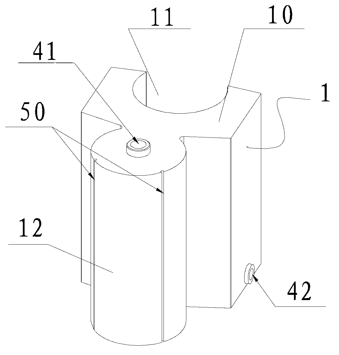
[0017] Each standard module 1 comprises a quadrangular prism body 10 that is provided with a circular arc groove 11 on one side and a circular arc post joint 12 protruding from the other side of the quadrangular prism body 11. Each standard module 1 is characterized by its circular arc post The joint 12 is rotatably inserted into the arc groove 11 of the adjacent standard module to connect;

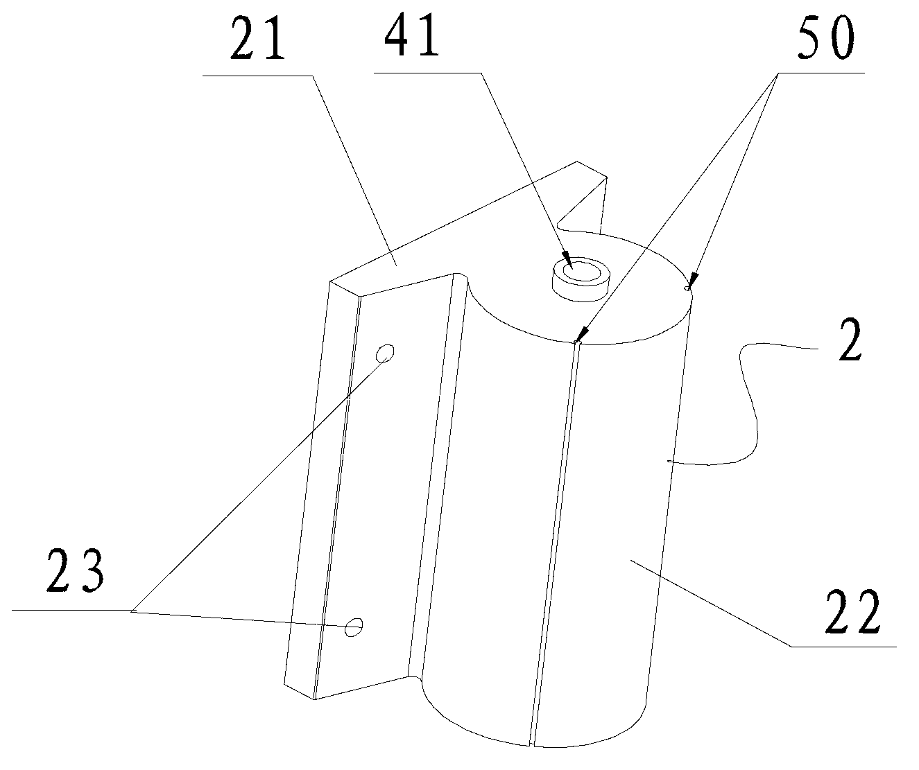
[0018] The first connection ...


PUM


Abstract

The invention discloses a cambered adjustable movable flood control wall which is low in manufacturing cost and convenient to convey and can be assembled quickly. The cambered adjustable movable flood control wall comprises a plurality of standard modules, a plurality of first connection modules and a plurality of second connection modules and is arranged between two building wall bodies, wherein each standard module comprises a quadrangular body and an arc column joint; an arc slot is formed in one side face of each quadrangular body, and each arc column joint is protruded out of the other side face of one quadrangular body; each standard module and the corresponding arc column joint of the standard module are connected with each other in a manner of being rotatably inserted into the arc slots of adjacent standard modules; each first connection module comprises a plate and an arc column joint connected to one side face of the plate; the arc column joints of the first connection modules are inserted into the arc slots of the adjacent standard modules in a rotatable manner; each second connection module comprises a quadrangular body and a T-shaped block; an arc slot is formed in one side face of each quadrangular body, and the T-shaped block is connected to the other side face of each quadrangular body; and the arc slots and the arc column joints of the adjacent standard modules are inserted in a rotatable manner. Water injection holes and water drainage holes are formed in the standard modules, the first connection modules and the second connection modules.

Description

technical field [0001] The invention relates to a flood control wall, in particular to an arc-shaped adjustable movable flood control wall. Background technique [0002] The rainy season from early June to mid-July and the typhoon season from mid-July to mid-September in my country's coastal areas are prone to flood disasters. When the flood season comes, many facilities such as underground garages, shopping malls, residential areas and other units with relatively low terrain must not only ensure a good drainage system, but also pile up some sandbags at the door to prevent ground water from flowing in and causing damage to vehicles or other property. Although stacking sandbags can have a better waterproof effect, due to the heavy weight of the sandbags, it takes more physical strength and time during the accumulation process. Besides, there are more fillers in the sandbags, plus the physical strength and time required during the accumulation process. Therefore the cost is h...

Claims


Application Information

Patent Timeline
IPC IPC(8): E02B3/10
Inventor 胡欣朱桦陈岩
Owner 上海东泽环境科技股份有限公司
Why Eureka
Try Eureka