Control circuit as well as switch converter and control method thereof

A technology for switching converters and control circuits, which is applied in circuit devices, regulating electrical variables, and control/regulating systems, etc., can solve problems such as circuit efficiency limitations, and achieve the effect of reducing static current and improving work efficiency.

Active Publication Date: 2013-03-06
CHENGDU MONOLITHIC POWER SYST
View PDF7 Cites 26 Cited by
  • Summary
  • Abstract
  • Description
  • Claims
  • Application Information

AI Technical Summary

Problems solved by technology

However, the quiescent current cannot be reduced without limit, so that the improvement of the circuit working efficiency is limited

Method used


Image

  • Control circuit as well as switch converter and control method thereof
  • Control circuit as well as switch converter and control method thereof
  • Control circuit as well as switch converter and control method thereof

Examples


Embodiment Construction

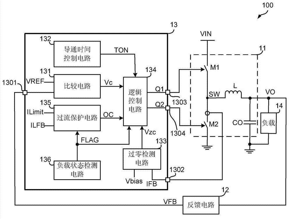
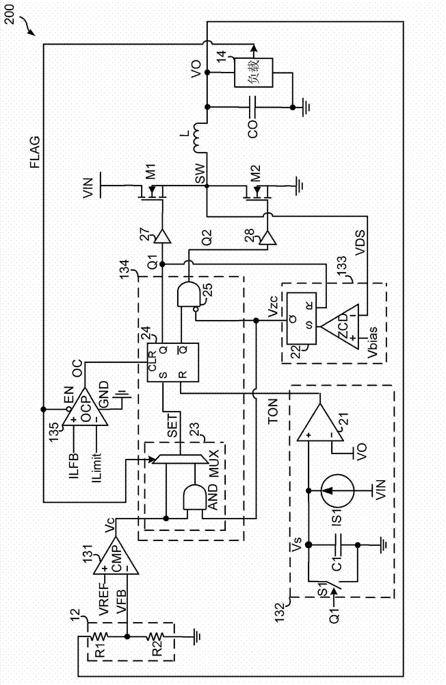
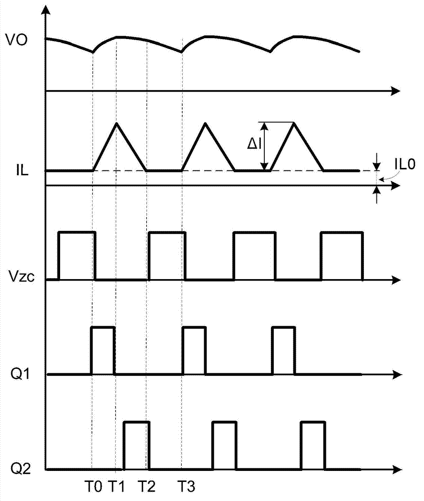
[0023] Specific embodiments of the present invention will be described in detail below, and it should be noted that the embodiments described here are only for illustration, not for limiting the present invention. In the following description, numerous specific details are set forth in order to provide a thorough understanding of the present invention. It will be apparent, however, to one of ordinary skill in the art that these specific details need not be employed to practice the present invention. In other instances, well-known circuits, materials or methods have not been described in detail in order to avoid obscuring the present invention.

[0024] Throughout this specification, reference to "one embodiment," "an embodiment," "an example," or "example" means that a particular feature, structure, or characteristic described in connection with the embodiment or example is included in the present invention. In at least one embodiment. Thus, appearances of the phrases "in on...


PUM


Abstract

The invention discloses a control circuit as well as a switch converter and a control method thereof. The switch converter comprises a power switching tube and a synchronous rectifying tube; the control circuit controls the power switching tube and the synchronous rectifying tube to be conducted and switched off; and when a control signal of a power saving mode is at an effective state, the conduction of the power switching tube is controlled through a comparing result of a feedback signal of output voltage and reference voltage, and a zeroing detection signal of current flowing through the synchronous rectifying tube, so that an extra over-current protection circuit is not needed, static current of the switch converter at the power saving mode is reduced, and the power of the switch converter at the power saving mode is improved.

Description

technical field [0001] The present invention mainly relates to an electronic circuit, in particular to a control circuit for a switching converter and a control method thereof. Background technique [0002] Along with the development of electronic technology, electronic devices such as mobile phones, personal digital assistants (PDAs), tablet computers, netbooks, and ultrabooks (Ultrabooks) are rapidly popularized. Ultrabooks, mobile phones, and other similar electronic devices need to have an always on and always connected (AOAC) function, that is, a standby function. Prolonging the time that the electronic device can maintain in the AOAC mode as much as possible or prolonging the standby time of the electronic device as much as possible has become one of the important indicators for designing the electronic device. Electronic devices have less power in AOAC or standby (standby) mode, and are in a light-load state. Therefore, the circuit operating efficiency at light load ...

Claims


Application Information

Patent Timeline
Patent Type & Authority Applications(China)
IPC IPC(8): H02M1/00H02M1/08H02M1/088H02M3/155
CPCY02B70/1466Y02B70/16H02H7/1213H02M3/158H02M3/1588H02M1/0032H02M1/0058Y02B70/10Y02B70/30Y04S20/20H02J9/005H02M3/156
Inventor 欧阳茜
Owner CHENGDU MONOLITHIC POWER SYST
Why Eureka
Try Eureka