DC-DC converter

A DC converter, inductor current technology, applied in the direction of converting DC power input to DC power output, high-efficiency power electronic conversion, output power conversion device, etc., can solve the problem that the output voltage ripple and static power consumption cannot be well controlled. And other issues

Active Publication Date: 2020-12-29
WUXI ETEK MICROELECTRONICS
View PDF5 Cites 9 Cited by
  • Summary
  • Abstract
  • Description
  • Claims
  • Application Information

AI Technical Summary

Problems solved by technology

[0010] Aiming at the problem that the traditional DCDC light-load control mode cannot well control the output voltage ripple and static power consumption, the present...

Method used


Image

  • DC-DC converter
  • DC-DC converter
  • DC-DC converter

Examples


Embodiment Construction

[0016] In order to make the above objects, features and advantages of the present invention more comprehensible, the present invention will be further described in detail below in conjunction with the accompanying drawings and specific embodiments.

[0017] Reference herein to "one embodiment" or "an embodiment" refers to a particular feature, structure or characteristic that can be included in at least one implementation of the present invention. "In one embodiment" appearing in different places in this specification does not all refer to the same embodiment, nor is it a separate or selective embodiment that is mutually exclusive with other embodiments. Unless otherwise specified, the words connected, connected, and joined in this document mean that they are electrically connected directly or indirectly.

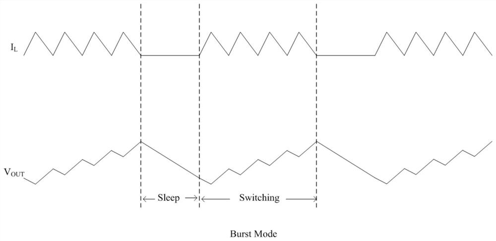
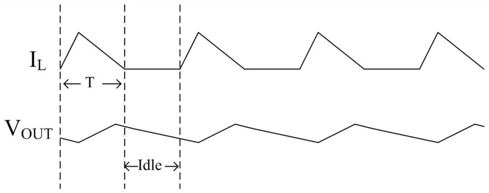
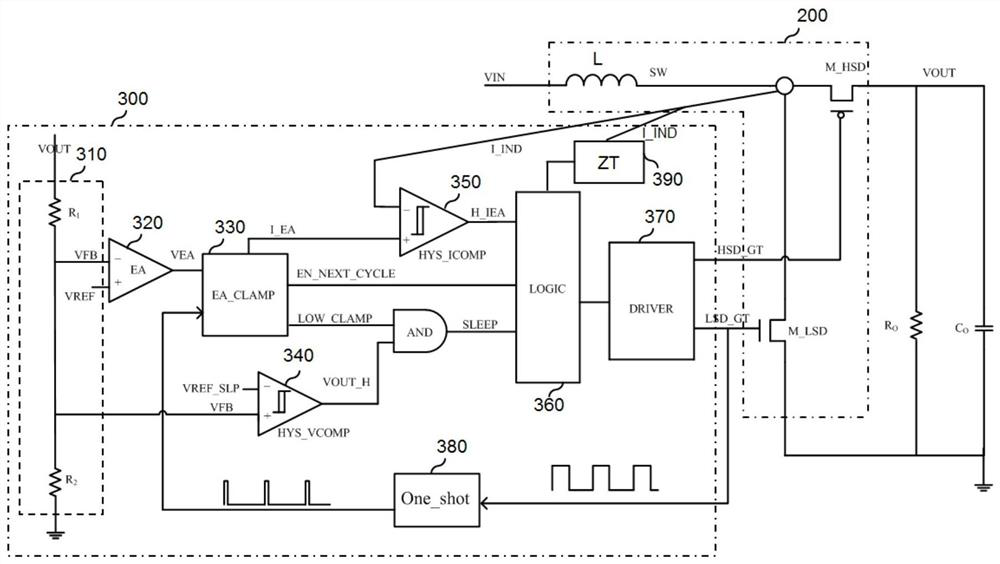
[0018] The present invention proposes a DC-DC converter, which can effectively reduce the ripple of the output voltage, and can also enter a dormant state under very light ...


PUM


Abstract

The invention provides a DC-DC converter. The converter comprises an output circuit which comprises an inductor, a first power transistor, and a second power transistor; and a control circuit which isconfigured to enter a dormant state from a monopulse mode when the load is lower than a preset value and the output voltage is larger than or equal to a first proportion of a set standard value, andreturn to the monopulse mode from the dormant state when the load is higher than the preset value or the output voltage is smaller than or equal to a second proportion of the set standard value; and in each period of the monopulse mode, the first power transistor is controlled to be switched on, the second power transistor is controlled to be switched off, then the first power transistor is controlled to be switched off, the second power transistor is controlled to be switched on, and when the inductive current reaches zero, if the period of the monopulse mode is not ended, the circuit entersan idle state. Therefore, ripples of the output voltage can be effectively reduced, and a dormant state can be entered when the load is extremely light, so that the quiescent current of the circuit isgreatly reduced.

Description

technical field [0001] The invention relates to the technical field of power conversion, in particular to a DC-DC converter. Background technique [0002] It is difficult for a DC-DC (direct current-direct current) converter with a traditional structure to meet the requirements of low ripple and low static power consumption at the same time at light load. In the traditional architecture, in order to obtain high efficiency and reduce standby power consumption at light load, burst mode (burst mode) is often used, and its waveform is as follows figure 1 shown. [0003] In this mode, when the output voltage VOUT is 1% higher than the set standard value, it enters the sleep state. When the output voltage is lower than 100.5% of the set standard value, it will exit the dormant state. Then the output ripple is at least VOUT*0.5%. However, due to the error and delay of circuits such as comparators, the light-load ripple using this method will be much larger than VOUT*0.5% in the...

Claims


Application Information

Patent Timeline
IPC IPC(8): H02M3/156H02M1/14H02M1/32
CPCH02M1/14H02M1/32H02M3/156H02M1/0048H02M1/322Y02B70/10
Inventor 谢凌寒袁敏民孙元良刘钰汪东
Owner WUXI ETEK MICROELECTRONICS
Why Eureka
Try Eureka