Control method of two-way direct current conversion device

A technology of bidirectional DC conversion and control method, which is applied in the field of control of bidirectional DC conversion devices, can solve problems such as complex circuits and poor phase shift of PWM driving waveforms, and achieve reduced interleaving number, simple design, and reduced current ripple Effect

Inactive Publication Date: 2013-04-10
BEIJING POWER MACHINERY INST
View PDF2 Cites 22 Cited by
  • Summary
  • Abstract
  • Description
  • Claims
  • Application Information

AI Technical Summary

Problems solved by technology

The fully interleaved parallel mode can effectively reduce the current ripple and reduce the switching loss, thereby improving work efficiency and reducing electromagnetic interference, but the driving waveform needs to be staggered at an angle of 360° / n. In the case of a large number of parallel connections, the higher the interleaved multiplicity More, the larger n is, the more complex the circuit is, and the precise PWM driving waveform phase shift is not easy to generate

Method used


Image

  • Control method of two-way direct current conversion device
  • Control method of two-way direct current conversion device
  • Control method of two-way direct current conversion device

Examples


Embodiment Construction

[0036] The present invention will be described in detail below with reference to the accompanying drawings and examples.

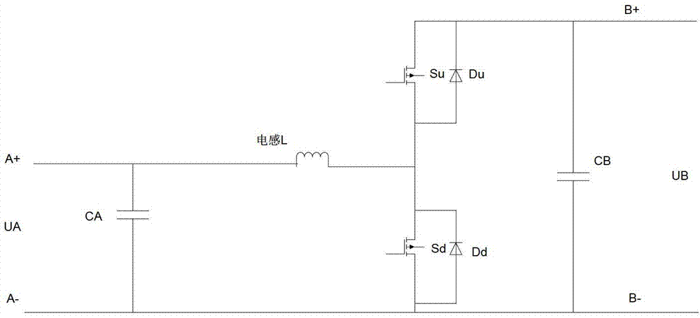
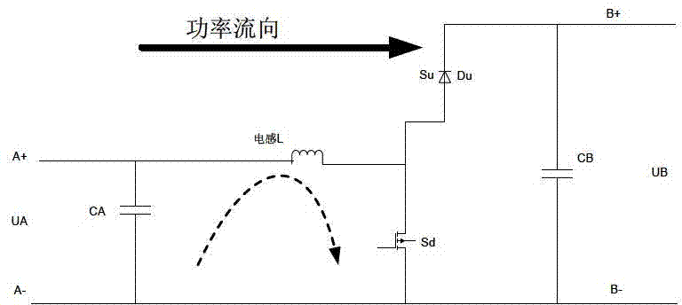
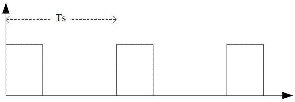
[0037] Aiming at the classic independent PWM control strategy, the present invention proposes a complementary PWM control strategy. The complementary PWM control strategy is to simultaneously control the complementary conduction of the upper and lower switching tubes within a cycle Ts. When the current is large, it is equivalent to the independent PWM control strategy. When the current is small The Buck state and Boost state are switched within one switching cycle, thereby ensuring the current continuity when the current is small, so only one control system is needed to ensure control accuracy.

[0038] Moreover, for high-power occasions, the switching devices (power switching tubes, freewheeling diodes, and energy transfer inductors) of the bidirectional DC conversion device are subjected to high voltage and current stress, causing serious radiation and co...


PUM


Abstract

The invention discloses a control method of a two-way direct current conversion device. The control method of the two-way direct current conversion device is suitable for high voltage and high power conversion sites, and can support frequent changing-over of power flow direction. Switching loss and circuit complexity can be balanced. At first an upper switch tube breakover time T 1 and a lower switch tube breakover time T 2 in a control cycle T s are calculated according to required pulse width modulation (PWM) control signal duty ratio D, and the ratio of T 1 to TS is D. In the process of practical control, one main circuit in the two-way direct current conversion device can be used as a reference subcircuit. The control on the reference subcircuit is that the upper switch tube and the lower switch tube in the reference subcircuit are controlled to be communicated in a complementary mode in each control circuit T s, and every time the upper switch tube and the lower switch tube are changed over, the dead time delta is added to carry out transition. Therefore the real breakover time of the upper switch tube is that T 1 subtracts the delta, and the real breakover time of the lower switch tube is that the T 2 subtracts the delta. The control on an un-referenced subcircuit is that control signals of all un-referenced subcircuits are the same, and differ by 180 degrees from the control signals of the reference circuit.

Description

technical field [0001] The invention relates to the technical field of power electronic converters, in particular to a control method for a bidirectional DC converter. Background technique [0002] With the development of aerospace power systems, fuel cells, wind power, photovoltaic power generation, electric vehicles and other new energy and new transmission technologies, bidirectional DC converters with bidirectional energy flow have a good application prospect. [0003] The bidirectional DC conversion device can realize bidirectional transmission of energy through the double-quadrant operation of the DC converter. Functionally equivalent to two unidirectional DC converters, it can be regarded as a "one machine with two uses, time-division multiplexing" equipment, widely used in occasions requiring two-way energy flow, suitable for UPS systems, power systems, electric vehicles and It is also suitable for the supplement of system sudden change energy in the occasion of ene...

Claims


Application Information

Patent Timeline
Patent Type & Authority Applications(China)
IPC IPC(8): H02M3/156
Inventor 霍雪娇张花王天亮俞凯朱明星黄尧
Owner BEIJING POWER MACHINERY INST
Why Eureka
Try Eureka