Boost charge pump circuit

A charge pump and circuit technology, which is applied in the direction of motor generator control, electrical components, sustainable manufacturing/processing, etc., can solve the problems of voltage regulator conversion efficiency drop, waste of energy, and charge pumps are difficult to meet, and achieve improved circuit conversion. Efficiency, differential stability, and power saving effects

Active Publication Date: 2014-03-19
JIAXING ZHONGRUN MICROELECTRONICS
View PDF3 Cites 22 Cited by
  • Summary
  • Abstract
  • Description
  • Claims
  • Application Information

AI Technical Summary

Problems solved by technology

Although a linear voltage regulator can effectively convert a fixed pump voltage into an adjustable output voltage Vout between Vin and 2*Vin, the voltage regulator causes a decrease in conversion efficiency and wastes energy
[0004] In addition, since the stepper motor driver requires the difference between the output voltage of the charge pump and the power supply voltage to remain constant, and the operating voltage of the stepper motor driver varies with the application system, it is difficult for the charge pump to meet the above requirements

Method used


Image

  • Boost charge pump circuit
  • Boost charge pump circuit
  • Boost charge pump circuit

Examples


Embodiment Construction

[0034] The foregoing and other objects, features, and advantages of the present invention will be more apparent from the following description and accompanying drawings. Here, specific embodiments according to the present invention will be described in detail with reference to the accompanying drawings.

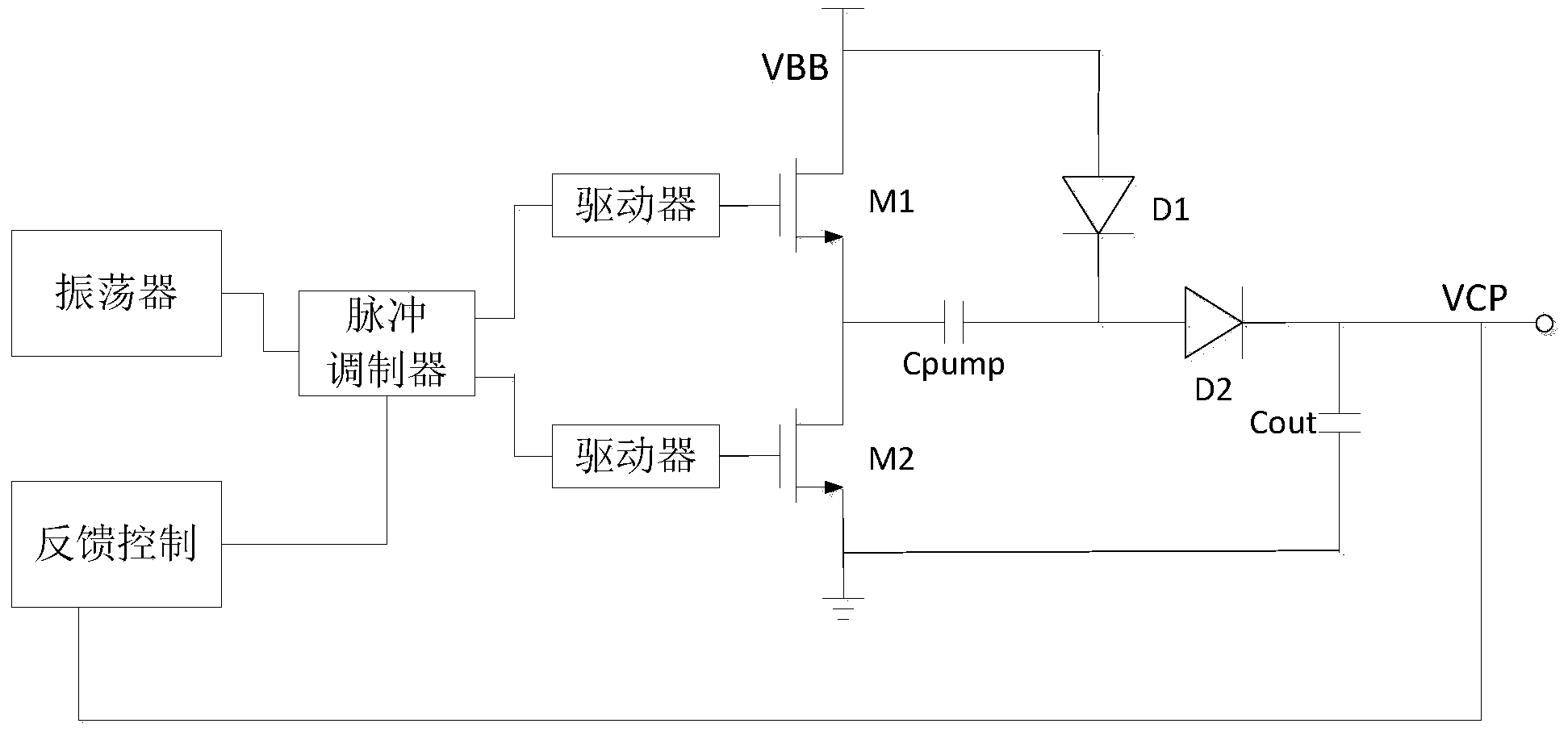
[0035] Such as image 3 As shown, the charge pump circuit of an embodiment of the present invention includes an output terminal Vout, a pair of NMOS switch tubes M1, M2, a pair of diodes D1, D2, a pump capacitor Cpump and a charging capacitor Cout, and the NMOS switch tubes M1, M2 and Diodes D1 and D2 form an H-bridge structure, the pump capacitor Cpump is connected between the source of the NMOS switch M1 and the cathode of the diode D1, and the charging capacitor Cout is connected between the cathode of the diode D2 and the ground;

[0036] The charge pump circuit in this embodiment also includes an oscillator, a pulse modulator, a first driver, a second driver, and a feed...


PUM


Abstract

The invention provides a boost charge pump circuit. The boost charge pump circuit omits a voltage regulator, utilizes feedback control to adjust an output voltage peak and guarantees that the output voltage is adaptable to step motor drivers of different applications; a boost charge pump continuously and repeatedly charge and discharge to maintain the stability of the output voltage, guarantees that the difference value of an output voltage value and a reference voltage are stable, enables output voltage ripples to be small and meets the requirements of the step motor drivers; a potential clamp module is utilized, the charging potential of a pump capacitor is limited, a circuit starting efficiency is improved, and accordingly power dissipation is reduced.

Description

technical field [0001] The invention relates to a charge pump circuit, in particular to a boosting charge pump circuit for a stepper motor driver. Background technique [0002] figure 1 A known charge pump circuit is shown, including a pump capacitor Cpump, an output capacitor Cout and a switch circuit; the working process of the charge pump circuit includes two stages, in the first stage, switches S1 and S4 are in a non-conductive state , the switches S2 and S3 are in the conduction state, so that one end NA of the pump capacitor Cpump is coupled to the ground, and the other end NB is coupled to the input voltage Vin, and the power supply charges the pump capacitor Cpump, so that the potential between the two ends NB and NA of the pump capacitor Cpump The difference rises to Vin; in the second stage, the switches S1 and S4 are in the conduction state, and the switches S2 and S3 are in the non-conduction state, so that the terminal NA of the pump capacitor Cpump is coupled ...

Claims


Application Information

Patent Timeline
Patent Type & Authority Applications(China)
IPC IPC(8): H02M3/07H02P8/00
CPCY02P80/10
Inventor 朱铁柱王良坤张明星夏存宝陈路鹏黄武康
Owner JIAXING ZHONGRUN MICROELECTRONICS
Why Eureka
Try Eureka