Control and drive circuit and method

A driving circuit and driving method technology, applied in the direction of electrical components, high-efficiency power electronic conversion, output power conversion devices, etc., can solve the problems of difficult transmission of duty ratio signals, increased circuit volume and cost, etc., to improve system efficiency, Effect of reducing cost and volume, suppressing common mode interference

Active Publication Date: 2013-03-13
SILERGY SEMICON TECH (HANGZHOU) CO LTD
View PDF3 Cites 11 Cited by
  • Summary
  • Abstract
  • Description
  • Claims
  • Application Information

AI Technical Summary

Problems solved by technology

However, since the transformer T 2 The existence of the circuit greatly increases the volume and cost, and the transformer T 2 Difficulty transmitting rapidly changing duty cycle signals

Method used


Image

  • Control and drive circuit and method
  • Control and drive circuit and method
  • Control and drive circuit and method

Examples


Embodiment 1

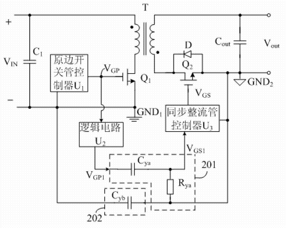
[0043] Such as Figure 2A The illustrated embodiment is a flyback synchronous rectification switching power supply. The flyback synchronous rectification switching power supply includes a power stage circuit and a driving circuit for converting the DC voltage V IN converted to the output voltage V out , wherein the power stage circuit includes a filter capacitor C 1 , transformer T, primary side switch tube Q 1 , Synchronous rectifier tube Q 2 and output filter capacitor C out ; The drive circuit includes the primary switch tube controller U 1 , logic circuit U 2 , conversion circuit 201 and synchronous rectifier controller U 3 . The primary switch tube controller U 1 Used to generate the control signal V of the primary switch tube GP to control the primary switch Q 1 is turned on and off, and its first output end is connected to the primary switch tube Q 1 The control terminal and the logic circuit U 2 The input terminal; the logic circuit U 2 used to receive th...

Embodiment 2

[0056] Such as image 3 The example shown is in the Figure 2A An improved flyback synchronous rectification switching power supply based on the circuit. and Figure 2A The difference of the flyback synchronous rectification switching power supply shown is that in order to protect the primary switching tube controller U 1 and the synchronous rectifier controller U 3 , this embodiment adds a first clamping circuit 301 and a second clamping circuit 302 . The first clamping circuit 301 includes a first diode D 1 , the second diode D 2 , the first clamping voltage V CLP1 and the second clamping voltage V CLP2 , the first diode D 1 The cathode is connected to the first clamping voltage V CLP1 , anode connected to the second diode D 2 The cathode of which is connected to the input end of the conversion circuit 201, and the second diode D 2 The anode is connected to the second clamping voltage V CLP2 ; The second clamping circuit 302 includes a third diode D 3 , the four...

Embodiment 3

[0064] Such as Figure 4 Shown is the forward synchronous rectification switching power supply in the third embodiment of the present invention. The forward synchronous rectification switching power supply includes a power stage circuit and a drive circuit, wherein the power stage circuit includes a filter capacitor C 1 , transformer T, primary side switch tube Q 1 , Synchronous rectifier tube Q 2 , Synchronous rectifier tube Q 3 and output filter capacitor C out ; The drive circuit includes the primary switch tube controller U 1 , logic circuit U 2 , conversion circuit 201 and synchronous rectifier controller U 3 . and Figure 2A The difference between the flyback synchronous rectification switching power supply in the first embodiment shown is that in this embodiment, the transformer T is connected to the terminal of the same name, and the synchronous freewheeling tube Q 3 with the output filter capacitor C out connected in parallel, the synchronous rectifier contr...


PUM


Abstract

The invention provides a control and drive circuit applied to a synchronous rectification switching mode power supply. The circuit comprises a primary switching tube controller, a logic circuit, a switching circuit and a synchronous rectifier tube controller, wherein the primary switching tube controller is used for generating a primary switching tube control signal, the logic circuit is used for generating a first control signal according to received primary switching tube control signal, the switching circuit is used for generating a second control signal according to the received first control signal, and the synchronous rectifier tube controller is used for generating a synchronous rectifier tube control signal according to the received second control signal and guaranteeing phases of the primary switching tube control signal and the synchronous rectifier tube control signal to be the same or inverse according to a topological structure of the synchronous rectification switching mode power supply. The invention further provides a control and drive method, so that the synchronous rectifier tube control signal for controlling on and off of a synchronous rectifier tube is generated according to the primary switching tube control signal, the problem of cross connection of the synchronous rectification power supply is solved, and high frequency, low cost, small size and high efficiency of the synchronous rectification switching mode power supply are achieved.

Description

technical field [0001] The invention relates to the field of switching power supplies, in particular to a control and drive circuit and method. Background technique [0002] With the development of switching power supply technology, low-voltage high-current switching power supply has become an important development trend, and the efficiency problem has always been a main theme of the development law of low-voltage high-current switching power supply. Synchronous rectification technology is a method commonly used to improve efficiency in low-voltage and high-current applications. Synchronous rectification technology can reduce the loss of synchronous rectification switching power supplies. The key of the synchronous rectification technology lies in the drive mode of the synchronous rectifier tube. Different drive modes have very different effects on the efficiency. [0003] see Figure 1A , what is shown in the figure is the first drive control mode of the existing flyback s...

Claims


Application Information

Patent Timeline
Patent Type & Authority Applications(China)
IPC IPC(8): H02M7/12
CPCY02B70/1475H02M3/33592Y02B70/10H02M1/08H02M3/33523H02M3/33553
Inventor 陈伟
Owner SILERGY SEMICON TECH (HANGZHOU) CO LTD
Why Eureka
Try Eureka