Continuous fiber-manufacturing device

A technology for manufacturing devices and fibers, applied in the field of electrospinning devices, can solve the problems of discontinuous liquid supply, coagulation of surface solution, large difference in jet size, etc.

Inactive Publication Date: 2013-05-22
XIAMEN UNIV
View PDF7 Cites 19 Cited by
  • Summary
  • Abstract
  • Description
  • Claims
  • Application Information

AI Technical Summary

Problems solved by technology

[0005] The purpose of the present invention is to provide a continuous fiber manufacturing device that can overcome the shortcomings of discontinuous liquid supply, large jet size differences, and surface solution solidification, and can ensure consistent fiber diameters and continuously electrospin nanofibers.

Method used


Image

  • Continuous fiber-manufacturing device
  • Continuous fiber-manufacturing device
  • Continuous fiber-manufacturing device

Examples


Embodiment Construction

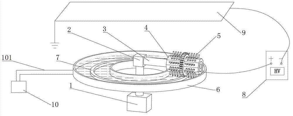
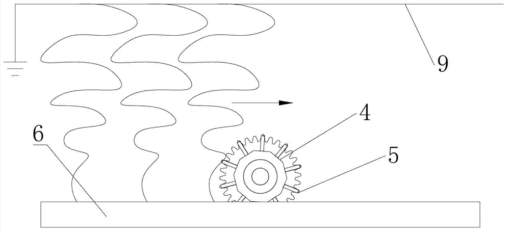
[0018] see figure 1 with 2 , the embodiment of the present invention is provided with a stepping motor 1, a connector 2, a rotating shaft 3, an inductive roller 4, a needle point array 5, an annular liquid storage tank 6, an annular rack 7, a DC high voltage power supply 8, a collecting plate 9 and a liquid supply device 10.

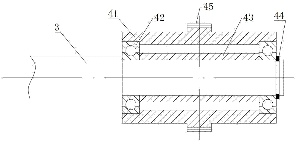
[0019] The output shaft of the stepping motor 1 is connected to the rotating shaft 3 through the connector 2, and the inducing roller 4 is connected to the rotating shaft 3 in rotation. The pinpoint array 5 is installed on the surface of the inducing roller 4, and each needlepoint of the pinpoint array 5 is connected to the threaded hole on the surface of the inducing roller 4 ( figure 1 with 2 not shown) screw connection. The induction roller 4 is composed of an induction wheel 41 , two ball bearings 42 , a sleeve 43 and a snap ring 44 , and the middle part of the induction wheel 41 is provided with a ring gear 45 . The inner ring of the ball beari...


PUM


Abstract

The invention discloses a continuous fiber-manufacturing device, relates to an electrostatic spinning device, and provides the fiber-manufacturing device capable of overcoming the shortcomings that liquid supply is not continuous and large in jet flow size difference, and surface solution solidifies and the like, and capable of guaranteeing uniformity of diameters of fiber and continuity of electrospinning nanometer fiber. The continuous fiber-manufacturing device is provided with a motor, a connector, a rotating shaft, an inducing rolling wheel, a needle tip array, an annular liquid-storage groove, a direct-current high-voltage power supply, a collection plate and a liquid-supplying device. An output shaft of the motor is connected with the rotating shaft through the connector. The inducing rolling wheel is connected with the rotating shaft in a rotating mode. Gear rings are arranged on the surface of the inducing rolling wheel. The needle tip array is arranged on the surface of the inducing rolling wheel. Annular racks are arranged inside the annular liquid-storage groove and are meshed with the gear rings of the inducing rolling wheel. The positive electrode of the direct-current high-voltage power supply is connected with an annular solution groove, and the negative of the direct-current high-voltage power supply is connected with the collection plate. The collection plate is arranged above the annular solution groove. The collection plate is grounded. The liquid-supplying device is communicated with the annular liquid-storage groove through a liquid-conveying pipe.

Description

technical field [0001] The invention relates to an electrostatic spinning device, in particular to a continuous fiber manufacturing device. Background technique [0002] Electrospinning has the characteristics of simple technology, low cost and pure physical stretching. It is very likely to become the mainstream manufacturing technology of nanofibers in the future. The efficiency of traditional electrospinning is extremely low, which seriously restricts the industrial application and commercialization of nanofibers. [0003] With the maturity of electrospinning technology and the in-depth application research of nanofibers, domestic and foreign researchers have conducted a lot of related research and made some progress on the bottleneck of low yield. [0004] Chinese patent CN200720076954.6 discloses a high-efficiency multi-needle electrospinning spinneret device, which is a natural extension of the traditional single nozzle. The mutual influence of the electric field betw...

Claims


Application Information

Patent Timeline
Patent Type & Authority Applications(China)
IPC IPC(8): D01D13/00D01D5/00
Inventor 孙道恒邱小椿黄少华吴德志刘益芳陈燕君
Owner XIAMEN UNIV
Why Eureka
Try Eureka