A kind of display and bonding method thereof

A technology for displays and substrates, applied in chemical instruments and methods, layered products, lamination devices, etc., can solve problems such as poor display effect of displays, and achieve the effect of improving display effect and ensuring the quality of lamination.

Active Publication Date: 2016-03-02
TRULY OPTO ELECTRONICS
View PDF4 Cites 0 Cited by
  • Summary
  • Abstract
  • Description
  • Claims
  • Application Information

AI Technical Summary

Problems solved by technology

[0004] However, the display effect of the display formed by applying the existing bonding method is relatively poor

Method used


Image

  • A kind of display and bonding method thereof
  • A kind of display and bonding method thereof
  • A kind of display and bonding method thereof

Examples


Embodiment 1

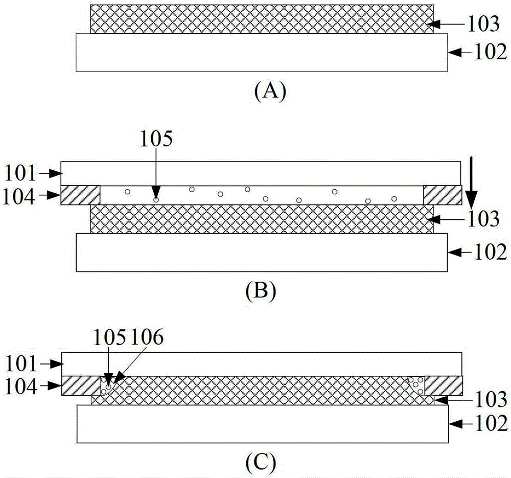
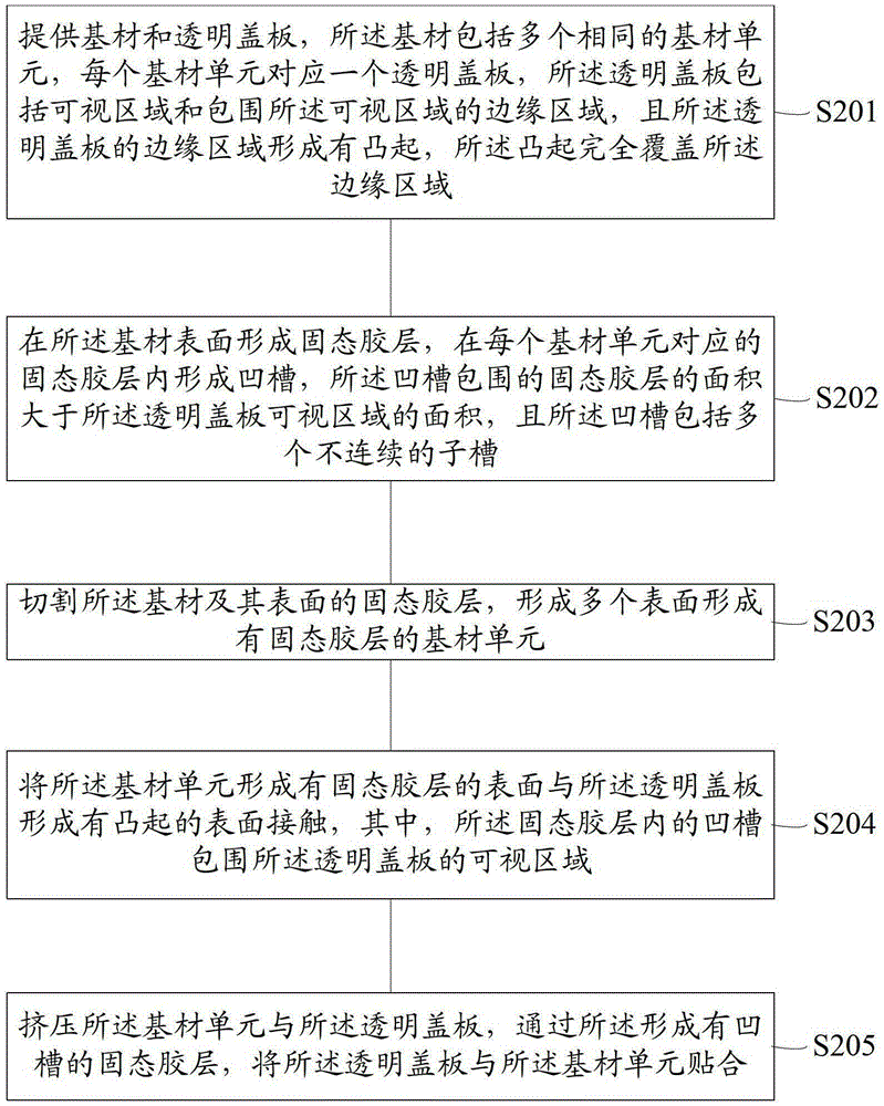
[0037] The flow chart of the bonding method disclosed in this embodiment is as follows figure 2 As shown, Figure 3-Figure 8 This is a schematic diagram of the bonding method provided in this embodiment. The bonding method specifically includes the following steps:

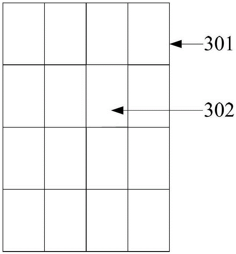
[0038] Step S201: such as image 3 with Figure 4 As shown, a substrate 301 and a transparent cover 303 are provided. The substrate includes a plurality of identical substrate units 302, and each substrate unit 302 corresponds to a transparent cover 303, the transparent cover 303 includes a visible area 304 and an edge area 305 surrounding the visible area, and the edge area 305 of the transparent cover 303 is formed with protrusions 306 that completely cover the edge area 305.

[0039] image 3 A substrate 301 is provided. The substrate 301 includes a plurality of substrate units 302, and the substrate units 302 and the transparent cover 303 are in a one-to-one correspondence, that is, the shape of the substrate unit ...

Embodiment 2

[0055] This embodiment provides a display with integrated touch function. This display is manufactured using the bonding method provided in the first embodiment, wherein the transparent cover is the cover of the display, and the protrusion is formed on The ink on the edge area of ​​the surface to be bonded of the cover plate, and the substrate is the touch function layer of the display.

[0056] The ink is opaque and is used to cover the non-transparent wiring inside the display, and play a role of decorating the display.

[0057] The substrate is used as the touch function layer of the display, and the types of the touch function include: resistive touch function layer, capacitive touch function layer, infrared touch function layer, surface acoustic wave touch function layer, etc. . Wherein, when the touch function layer is a capacitive touch function layer, the touch function layer is preferably an ITO film layer.

[0058] It should be noted that the types of displays with integr...


PUM

PropertyMeasurementUnit
heightaaaaaaaaaa
thicknessaaaaaaaaaa
widthaaaaaaaaaa

Abstract

The invention provides a laminating method, and is applied to the manufacturing process of a display. The laminating method comprises the following steps of: providing base material and a transparent cover plate, wherein the base material comprises a plurality of same base material units; forming a solid adhesive layer on the surface of the base material, and forming a groove inside the solid adhesive layer corresponding to each base material unit; contacting the surfaces of the base material units provided with the solid adhesive layer with the surface of the transparent cover plate provided with bulges, and extruding the base material units and the transparent cover plate; and laminating the transparent cover plate and the base material units through the solid adhesive layer provided with the grooves. According to the laminating method, gas between the transparent cover plate and the base material units can be extruded into the grooves of the solid adhesive layer during the laminating process, and the grooves and bubbles inside the grooves cannot influence the display effect of the transparent cover plate, so that the display effect of the transparent cover plate is prevented from being influenced by the bubbles simultaneously when the laminating quality between the transparent cover plate and the base material units is ensured.

Description

Technical field [0001] The invention belongs to the manufacturing field of displays, and particularly relates to a display and a bonding method thereof. Background technique [0002] With the increasing of multimedia equipment, displays, as an important part of multimedia equipment, have begun to become an important branch of the technological development of multimedia equipment today, including touch displays and liquid crystal displays. [0003] Current multimedia displays involve laminating technology in the manufacturing process. Laminating technology requires that the two components of the display (such as the transparent cover of the display and the substrate) are combined through a solid glue layer. In the existing bonding process, a substrate with a relatively flat surface to be bonded is selected, a solid glue layer is formed on the relatively flat surface of the substrate, and then the substrate is bonded to the transparent cover through the solid glue layer , So that th...

Claims


Application Information

Patent Timeline
Patent Type & Authority Patents(China)
IPC IPC(8): B32B37/12
Inventor 李伟界周伟杰陈铿锵李建华
Owner TRULY OPTO ELECTRONICS
Why Eureka
Try Eureka