Threaded sliding sleeve with ball seat capable of being taken out

A threaded and ball-seat technology, which is applied in the direction of mining fluid, wellbore/well components, earthwork drilling and production, etc., can solve the problems of inconvenient tools and inability to discharge pipe string parts, and achieve the effect of not easy to fall off and safe and reliable connection

Active Publication Date: 2013-09-25
BC P INC CHINA NAT PETROLEUM CORP +1
View PDF9 Cites 9 Cited by
  • Summary
  • Abstract
  • Description
  • Claims
  • Application Information

AI Technical Summary

Problems solved by technology

In response to this situation, after the fracturing construction, the inner ball seat fishing tool can be lowered to salvage all the inner ball seats at one time, so as to reduce the fishing time and greatly improve the work efficiency. Finally, there will be residual parts in the pipe string that cannot be discharged, which will cause inconvenience to the entry of subsequent tools

Method used


Image

  • Threaded sliding sleeve with ball seat capable of being taken out
  • Threaded sliding sleeve with ball seat capable of being taken out
  • Threaded sliding sleeve with ball seat capable of being taken out

Examples


Embodiment Construction

[0015] The structure of the one-pass thread type removable ball seat sliding sleeve of the present invention will be described in detail below in conjunction with the accompanying drawings.

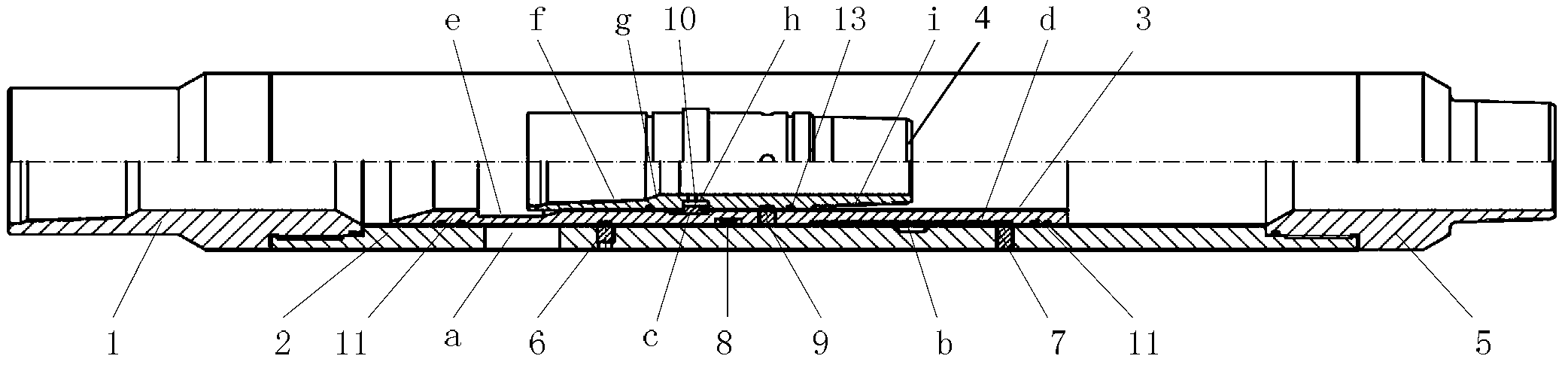
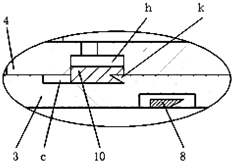
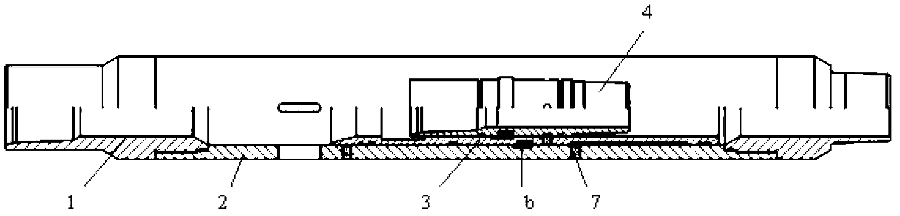
[0016] see figure 1 with figure 2 The one-pass threaded ball seat sliding sleeve of the present invention includes a sliding sleeve body composed of an upper joint 1, an outer cylinder 2 and a lower joint 5 which are threaded in sequence, an inner sliding sleeve 3 installed in the outer cylinder 2 and The ball seat cylinder 4 arranged in the inner sliding sleeve 3, the sliding sleeve body and the inner sliding sleeve 3 are fixed by the shear nails 6, the inner sliding sleeve 3 and the ball seat cylinder are fixed by the shear nails 9, the inner sliding sleeve Seal rings 11 are used to seal between the two ends and the body of the sliding sleeve.

[0017] A liquid outlet hole a is arranged on the upper part of the outer cylinder 2, and a spring hole b is arranged on the lower part of th...


PUM


Abstract

The invention discloses a threaded sliding sleeve with a ball seat capable of being taken out. The threaded sliding sleeve comprises a sliding sleeve body, an inner sliding sleeve and a ball seat cylinder, wherein the sliding sleeve body is composed of an upper connector, an outer cylinder and a lower connector, a fluid outlet hole is formed in the upper portion of the outer cylinder, and a clamp spring hole is formed in the lower position of the middle of the inner wall of the outer cylinder; a switch clamp groove is formed in the inner wall of the upper portion of the inner sliding sleeve, a locking ring groove is formed in the inner wall of the middle of the inner sliding sleeve, a locking ring is fixed at the lower portion of the locking ring groove, the length of the locking ring is smaller than that of the locking ring groove, a clamp spring is installed on the outer wall of the middle of the inner sliding sleeve, and an anti-rotating groove extending in the axial direction is formed in the outer wall of the lower portion of the inner sliding sleeve; a sliding sleeve shear pin is installed at the position, corresponding to the lower end of the anti-rotating groove, on the outer cylinder, and the upper end of the sliding sleeve shear pin stretches into the anti-rotating groove; threads are formed on the inner side of the upper end of the ball seat cylinder and on the outer side of the lower end of the ball seat cylinder, the outer diameter of the lower end of the ball seat cylinder is the same with the inner diameter of the upper end of the ball seat cylinder, a ball seat locking ring groove is formed in the outer periphery of the ball seat cylinder, and the inner side of the locking ring stretches into the ball seat locking ring groove. Salvage of all ball seat cylinders in a tubular column can be achieved, and a full path of an underground pipe string is achieved.

Description

technical field [0001] The invention relates to the field of oil and gas field exploitation, in particular to an optional ball seat sliding sleeve used for supporting the staged fracturing technology. Background technique [0002] At present, the multi-stage fracturing reconstruction of horizontal wells in oil and gas fields generally adopts oil layer special drilling technology and hanging packers, sliding sleeves, open hole packers and supporting tools to realize multi-stage fracturing, or uses cementing sliding sleeves and supporting tools for cementing. Multistage fracturing. Horizontal well staged fracturing sleeves include ball-throwing sleeves and differential pressure opening sleeves. The ball-throwing sleeve technology is to open the sliding sleeve of the fracturing switch by throwing low-density balls, exposing the communication hole between the oil layer and the tubing, and connecting Oil pipe and oil layer. Compared with the differential pressure sliding sleeve...

Claims


Application Information

Patent Timeline
Patent Type & Authority Applications(China)
IPC IPC(8): E21B43/26E21B34/14
Inventor 冯强王瑶郭鸣程智远何志勇
Owner BC P INC CHINA NAT PETROLEUM CORP
Why Eureka
Try Eureka