Rotation-free locking ring type sliding sleeve with ball seat capable of being taken out

A ball seat and ring type technology, applied in the field of non-rotation locking ring type removable ball seat sliding sleeve, can solve the problems of tool jamming, fishing action ground cannot be accurately judged, etc., and achieve easy unlocking, low salvage cost, and reliable locking Effect

Inactive Publication Date: 2013-09-25
CNPC BOHAI DRILLING ENG
View PDF5 Cites 5 Cited by
  • Summary
  • Abstract
  • Description
  • Claims
  • Application Information

AI Technical Summary

Problems solved by technology

At present, the commonly used ball seat fishing method is threaded fishing, which needs to rotate the fishing tool to complete the threaded connection during the fishing process. Therefore, this type of method cannot be used for non-rotating strings such as coiled tubing and steel wires, and the fishing action of the sliding sleeve The ground cannot be accurately judged, and the salvage situation can only be known after the salvage string is fully lifted, and the ball seat locking device after salvage remains in the tool, which will cause a risk of jamming for subsequent tools

Method used


Image

  • Rotation-free locking ring type sliding sleeve with ball seat capable of being taken out
  • Rotation-free locking ring type sliding sleeve with ball seat capable of being taken out
  • Rotation-free locking ring type sliding sleeve with ball seat capable of being taken out

Examples


Embodiment approach

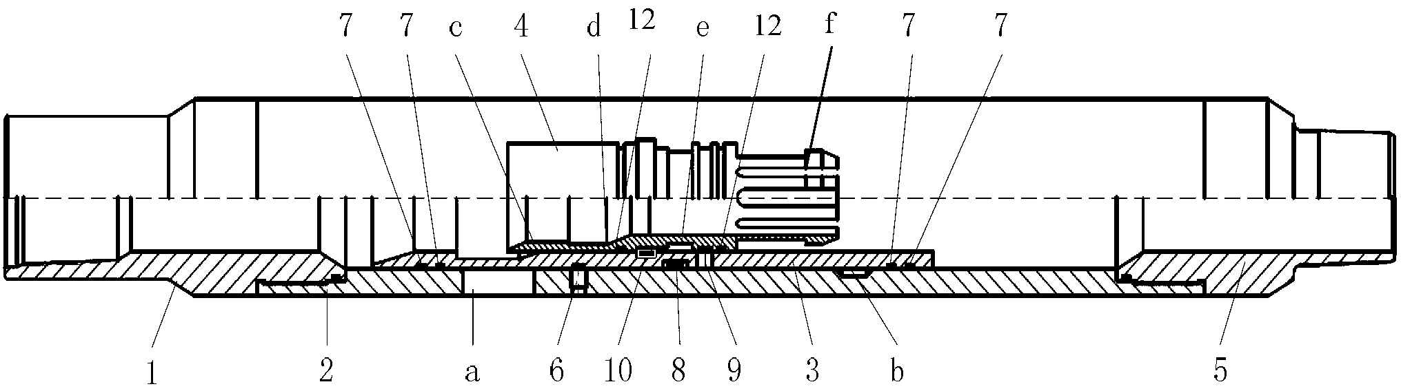
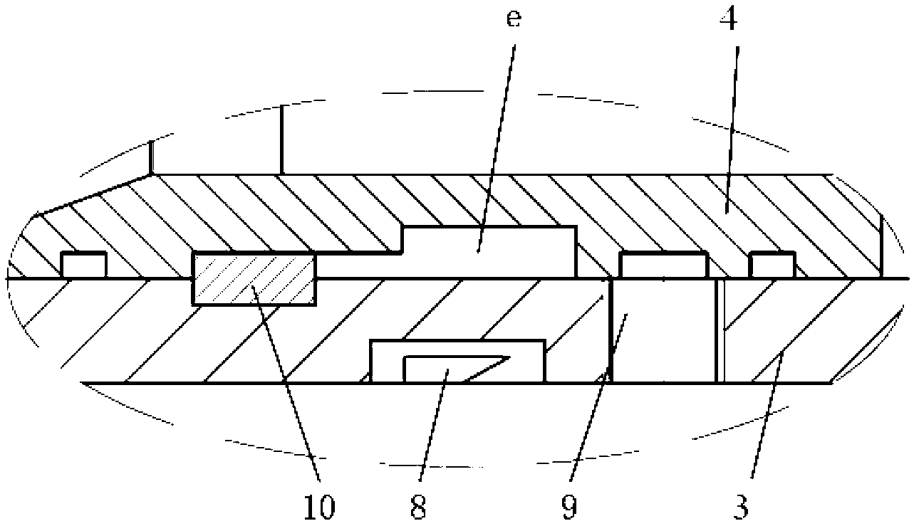
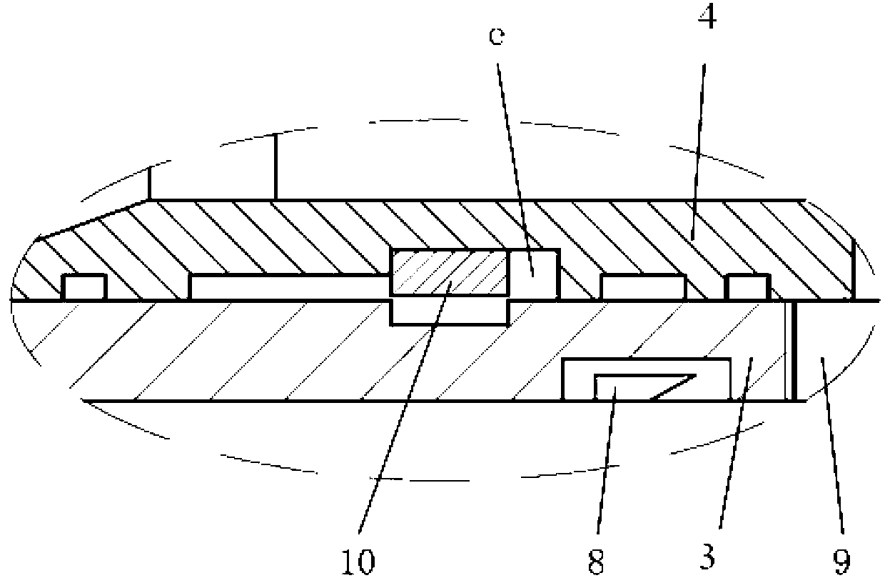
[0029] The implementation method of the free-rotation locking ring type removable ball seat sliding sleeve of the present invention is as follows:

[0030] Firstly, lower the sliding sleeves of all levels into the designated positions, put in the ball with the smallest diameter, and the ball falls into the variable-diameter ball seat e with the smallest inner diameter at the bottom of the wellbore, and press down to make the ball seat generate a downward force, driving the inner sliding sleeve 3 to face each other. The outer cylinder 2 moves down, the shear pin 6 is cut off to open the sliding sleeve, and when the snap ring 8 moves down to the position of the lock ring groove b, it snaps into the lock ring groove b, thereby limiting the further downward movement of the inner sliding sleeve 3 . In this way, open all the sliding sleeves from bottom to top in turn. Then, drop in Figure 4 For the fishing tool shown, the male pawl g of the fishing tool is inserted into the female...


PUM


Abstract

The invention discloses a rotation-free locking ring type sliding sleeve with a ball seat capable of being taken out. The sliding sleeve comprises a sliding sleeve body, an inner sliding sleeve and a ball seat cylinder, wherein the sliding sleeve body is composed of an upper connector, an outer cylinder and a lower connector. The sliding sleeve body and the inner sliding sleeve are fixed through a shear nail, the inner sliding sleeve and the ball seat cylinder are fixed through a shear nail, a fluid outlet hole is formed in the upper portion of the outer cylinder, and a clamping spring hole is formed in the inner wall of the outer cylinder. A switch clamping groove is formed in the inner wall of the upper portion of the inner sliding sleeve, a clamping spring is installed on the outer wall of the middle of the inner sliding sleeve, and a locking ring is installed in the peripheral direction of the inner wall of the middle of the inner sliding sleeve. A plurality of female pawls are arranged on the inner side of the upper end of the ball seat cylinder in the peripheral direction, a plurality of male pawls are arranged at the lower end of the ball seat cylinder in the peripheral direction, and the middle of the inner wall of the ball seat cylinder protrudes inwards for forming a variable diameter ball seat. An inwards-concave step-shaped locking ring groove is formed in the middle of the outer wall of the ball seat cylinder, and the inner side of the locking ring is clamped in the upper portion of the locking ring groove. When the inner sliding sleeve moves to the lower end of the outer cylinder, the clamping spring on the inner sliding sleeve is clamped into the clamping spring hole in the outer cylinder. All base seat cylinders can be salvaged through the sliding sleeve in a disposable mode, and a full through path is achieved.

Description

technical field [0001] The invention relates to the field of oil and gas field exploitation, in particular to a one-pass rotation-free locking ring type removable ball seat sliding sleeve. Background technique [0002] At present, the multi-stage fracturing reconstruction of horizontal wells in oil and gas fields generally adopts oil layer special drilling technology and hanging packers, sliding sleeves, open hole packers and supporting tools to realize multi-stage fracturing, or uses cementing sliding sleeves and supporting tools for cementing. Complete multi-stage fracturing. Horizontal well staged fracturing sleeves include ball-throwing sleeves and differential pressure opening sleeves. The ball-throwing sleeve technology is to open the sliding sleeve of the fracturing switch by throwing low-density balls, exposing the communication hole between the oil layer and the tubing, and connecting Oil pipe and oil layer. Compared with the differential pressure sliding sleeve, ...

Claims


Application Information

Patent Timeline
Patent Type & Authority Applications(China)
IPC IPC(8): E21B43/26E21B34/14
Inventor 冯强王瑶郭鸣程智远何志勇
Owner CNPC BOHAI DRILLING ENG
Why Eureka
Try Eureka