Vertical shaft spiral-flow type inner energy dissipater used for discharging ecological flows

A technology of ecological flow and internal energy dissipation, which is applied in water conservancy projects, sea area engineering, coastline protection, etc., can solve the problem of no internal energy dissipation suitable for small flows, and achieve novel structure, significant engineering benefits, and energy dissipation layout flexible effects

Active Publication Date: 2013-10-16
CHINA WATER NORTHEASTERN INVESTIGATION DESIGN & RES
View PDF9 Cites 2 Cited by
  • Summary
  • Abstract
  • Description
  • Claims
  • Application Information

AI Technical Summary

Problems solved by technology

[0009] The invention provides a vertical shaft swirling internal energy dissipator used for ecological flow discharge to solve the problem that there is no internal energy dissipator suitable for small flow at present

Method used


Image

  • Vertical shaft spiral-flow type inner energy dissipater used for discharging ecological flows
  • Vertical shaft spiral-flow type inner energy dissipater used for discharging ecological flows
  • Vertical shaft spiral-flow type inner energy dissipater used for discharging ecological flows

Examples


Embodiment 1

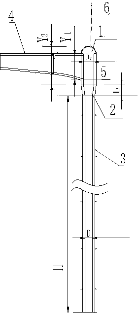
[0040] There is a ventilation hole 6 in the middle of the top of the vortex chamber, the bottom of the vortex chamber is connected to the shaft 3 through the shaft contraction section 2, and the water diversion section 4 at the inlet of the vortex chamber is connected to the side of the vortex chamber 1;

[0041] Determination of the diameter D of the shaft 3:

[0042]

[0043] In the formula:

[0044] D - shaft diameter;

[0045] Q——design flow rate, take 4.4m 3 / s;

[0046] g—gravitational acceleration, take g=9.8 (m / s 2 );

[0047] k——Correction coefficient, take k=1;

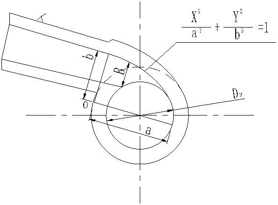
[0048] Vortex chamber 1 diameter D v OK for:

[0049] D. v =1.2D;

[0050] The inlet water diversion section 4 of the vortex chamber adopts an elliptical contraction type, and the side wall of the vortex chamber and the inlet water diversion section of the vortex chamber is connected by a 1 / 4 elliptic curve, and the major axis of the ellipse is a=1.2D v , minor axis b=0.75 D v ;

[0051] The det...

Embodiment 2

[0064] There is a ventilation hole 6 in the middle of the top of the vortex chamber, the bottom of the vortex chamber is connected to the shaft 3 through the shaft contraction section 2, and the water diversion section 4 at the inlet of the vortex chamber is connected to the side of the vortex chamber 1;

[0065] Determination of the diameter D of the shaft 3:

[0066]

[0067] In the formula:

[0068] D - shaft diameter;

[0069] Q——design flow rate, take 4.4m 3 / s;

[0070] g—gravitational acceleration, take g=9.8 (m / s 2 );

[0071] k——correction coefficient, take k= 1.12;

[0072] Vortex chamber 1 diameter D v OK for:

[0073] D. v =1.3D;

[0074] The inlet water diversion section 4 of the vortex chamber adopts an elliptical contraction type, and the side wall of the vortex chamber and the inlet water diversion section of the vortex chamber is connected by a 1 / 4 elliptic curve, and the major axis of the ellipse is a=1.2D v , minor axis b=0.75 D v ;

[0075] T...

Embodiment 3

[0088] There is a ventilation hole 6 in the middle of the top of the vortex chamber, the bottom of the vortex chamber is connected to the shaft 3 through the shaft contraction section 2, and the water diversion section 4 at the inlet of the vortex chamber is connected to the side of the vortex chamber 1;

[0089] Determination of the diameter D of the shaft 3:

[0090]

[0091] In the formula:

[0092] D - shaft diameter;

[0093] Q——design flow rate, take 4.4m 3 / s;

[0094] g—gravitational acceleration, take g=9.8 (m / s 2 );

[0095] k——correction coefficient, take k=1.25;

[0096] Vortex chamber 1 diameter D v OK for:

[0097] D. v ==1.4D;

[0098] The inlet water diversion section 4 of the vortex chamber adopts an elliptical contraction type, and the side wall of the vortex chamber and the inlet water diversion section of the vortex chamber is connected by a 1 / 4 elliptic curve, and the major axis of the ellipse is a=1.2D v , minor axis b=0.75 D v ;

[0099] D...


PUM


Abstract

The invention relates to a vertical shaft spiral-flow type inner energy dissipater used for discharging ecological flows and belongs to inner energy dissipaters of hydraulic and hydropower engineering ecological flow discharging. An air hole is formed in the center of the top of a volute chamber, the lower portion of the volute chamber is connected with a vertical shaft through a vertical shaft contraction section, and an inlet water diversion section of the volute chamber is connected with the side face of the volute chamber. The vertical shaft spiral-flow type inner energy dissipater has the advantages of being novel in structure. In comparison with a conventional energy dissipation technology, vertical shaft spiral-flow type inner energy dissipater is flexible in vertical shaft spiral-flow type energy dissipation arrangement, high in adaptability to an engineering geological condition and high in energy dissipation rate, and the energy dissipation rate can reach above 85%. In comparison with a conventional energy dissipation valve chamber scheme, more than 1000 millions of investments can be saved, the engineering effect is obvious, and the vertical shaft spiral-flow type inner energy dissipater has wide popularization value.

Description

technical field [0001] The invention relates to a new type of internal energy dissipator used for the discharge of ecological flow in water conservancy and hydropower projects. Specifically, the current minimum flow at home and abroad is only 4.4m 3 / s shaft swirl internal energy dissipator. Background technique [0002] During the development and construction of hydropower stations, regional economic development and power generation benefits were considered more in the past, while protection of the ecological water environment was less considered. Problems such as the deterioration of the water environment in the downstream river sections caused by the construction of water conservancy and hydropower projects have become more and more serious. The more it attracts the attention of all sectors of society, especially the diversion type and hybrid hydropower stations, since there will be a certain water reduction (dewatering) section between the dam and the power plant, the fo...

Claims


Application Information

Patent Timeline
Patent Type & Authority Applications(China)
IPC IPC(8): E02B8/06
Inventor 苏加林路振刚齐志坚顾一新王超张正平李正国王永潭杨克迟明德徐怀聚祁世京李桂芳张殿双王谊付欣郑军郭学仲宗原李大伟
Owner CHINA WATER NORTHEASTERN INVESTIGATION DESIGN & RES
Why Eureka
Try Eureka