Lamp far-end control system

A technology of remote control and lamps, which is applied in the direction of electric lamp circuit layout, lighting devices, light sources, etc., and can solve problems such as accidents caused by passers-by, vast street lamp configuration, and the inability to actually grasp the operating status of street lamps.

Inactive Publication Date: 2013-11-06
JUSTING TECH
View PDF5 Cites 1 Cited by
  • Summary
  • Abstract
  • Description
  • Claims
  • Application Information

AI Technical Summary

Problems solved by technology

[0005] The above conventional street lamp control methods may achieve the expected control effect of automatically controlling the street lamps to be turned on or off, but it is impossible to actually grasp the operating status of each street lamp; In such a location, the relevant management personnel cannot inspect whether the street lights are operating normally as expected, and only after other passers-by find out and inform the management unit passively can they find that the street lights are not turned on or damaged as expected. An unexpected crisis happened to passers-by

Method used


Image

  • Lamp far-end control system
  • Lamp far-end control system
  • Lamp far-end control system

Examples


Embodiment Construction

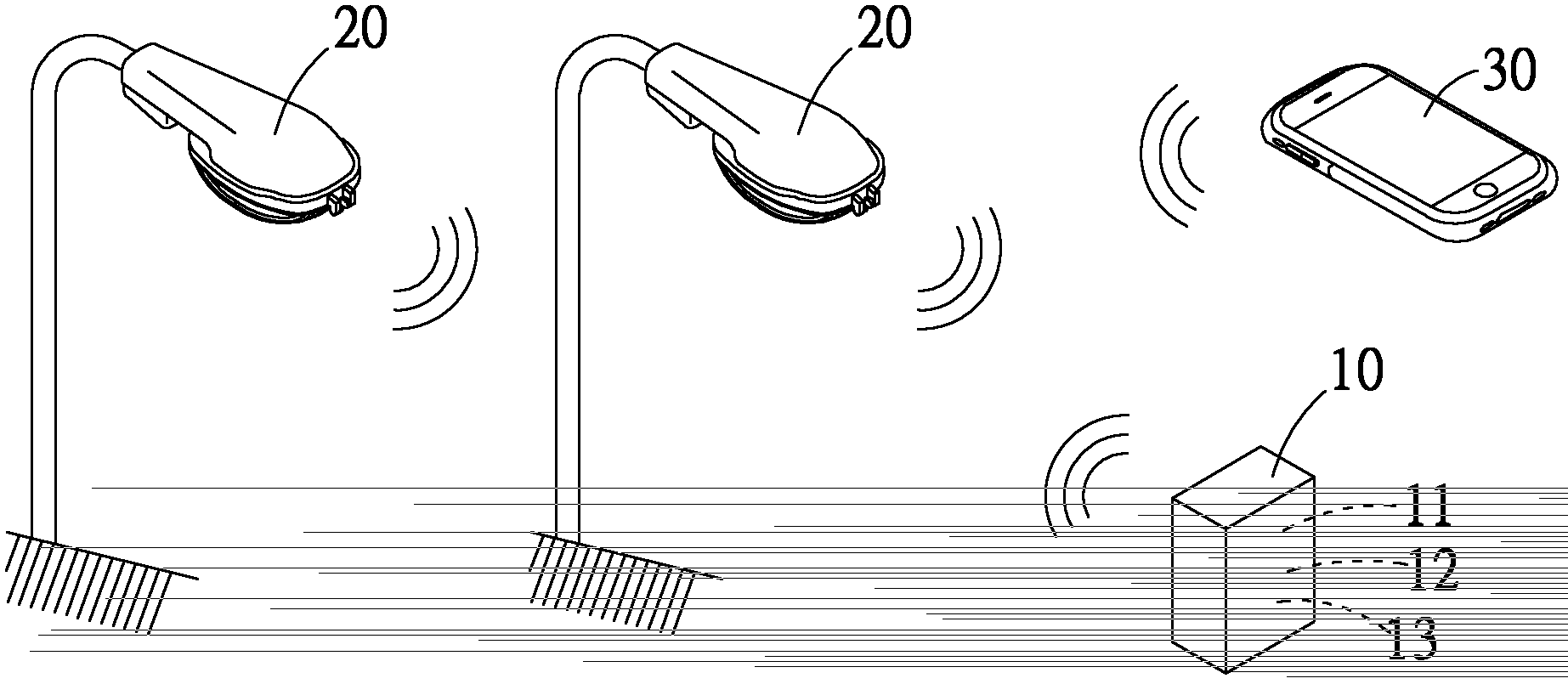
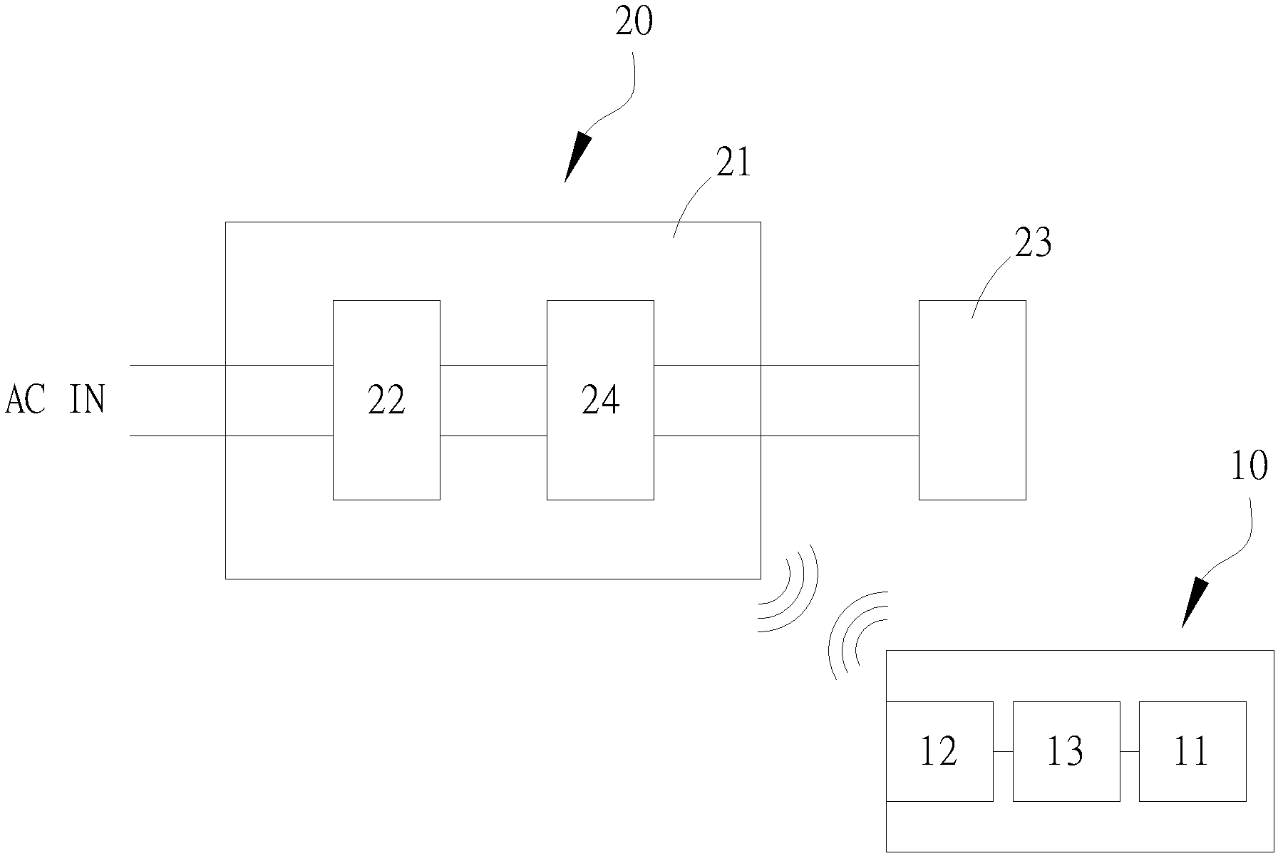
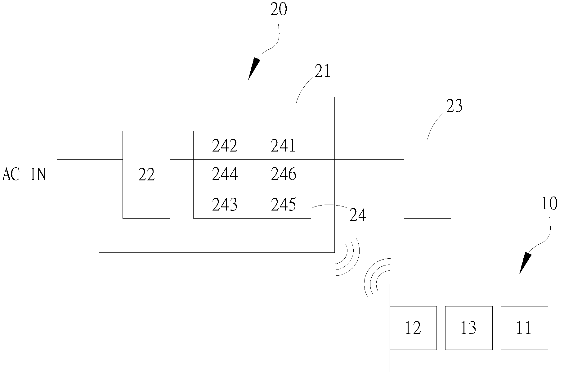
[0046] like figure 1 As shown in the structure diagram of the lamp remote monitoring system of the present invention, the present invention mainly provides a lamp remote monitoring system in which the remote host 10 grasps the operating status of each lamp 20 and controls the operation of each lamp 20 through wireless transmission. , the overall lighting remote monitoring system has a remote host 10, and at least one lamp 20; the remote host 10 has a built-in monitoring software 11, and is electrically connected to a first wireless transmission / reception module 12, a The first power amplifying module 13 for amplifying the signal wave sent by the first wireless transmitting / receiving module 12; during implementation, the first wireless transmitting / receiving module 12 has a built-in IEEE interface, and the first power amplifying module The group 13 is built with an amplifier for amplifying the signal pre-transmitted to the first wireless transmission / reception module 12 .

[0...


PUM


Abstract

The invention relates to a lamp far-end control system which comprises a far-end host machine and at least one lamp. Monitoring software is arranged in the far-end host machine, and a first wireless transmitting / receiving module and a first power amplification module are electrically connected to the far-end host machine. An alternating current and direct current converter for being connected with a power source, a photoelectric module and a control circuit electrically connected between the alternating current and direct current converter and the photoelectric module are arranged on a lamp body of each lamp, wherein each control circuit comprises a light adjusting module, a current stabilizing / voltage stabilizing module, a second wireless transmitting / receiving module, a voltage / current detecting module, a second power amplification module and a signal processing module in an integrated mode. The lamp far-end control system mainly achieves the purposes that the operation states of all the lamps are controlled by the far-end host machine, and therefore the operation of all the lamps are controlled by the utilization of the voltage / current information output to the photoelectric module through the normal state detection of the voltage / current detecting module and through information transmission carried out between the second wireless transmitting / receiving module and the first wireless transmitting / receiving module of the far-end host machine.

Description

technical field [0001] The present invention relates to a lamp monitoring technology, in particular to a lamp remote monitoring and control system that receives lamp operation information through wireless transmission, or sends control signals to the lamp. Background technique [0002] By the way, electric light should be regarded as the most widely used optoelectronic technology at present, and it is also one of the greatest inventions of mankind; as we all know, general lighting fixtures can be generally installed indoors and outdoors in buildings, or used for portable use, and connected Appropriate power supply and related circuit switches can be used for users to freely control lighting fixtures to turn on or off according to actual needs. [0003] In order to improve the safety of driving at night or pedestrians going out, most government departments will also install street lights on both sides of ordinary roads or in outdoor public areas such as parks; moreover, light...

Claims


Application Information

Patent Timeline
Patent Type & Authority Applications(China)
IPC IPC(8): H05B37/02
Inventor 苏佳庆余渊铭詹东融陈清木陈慎铫
Owner JUSTING TECH
Why Eureka
Try Eureka