Hydraulic damper with actively-adjustable damping

A hydraulic shock absorber and damping technology, applied in the field of hydraulic shock absorbers, can solve the problems of high manufacturing cost, complex structure, unstable performance of shock absorbers, etc., and achieve the effects of reliable performance, low requirements and cost reduction.

Inactive Publication Date: 2013-12-04
JIANGSU UNIV
View PDF5 Cites 13 Cited by
  • Summary
  • Abstract
  • Description
  • Claims
  • Application Information

AI Technical Summary

Problems solved by technology

[0005] In order to solve the problems of unstable performance, complex structure and high manufacturing cost of existing shock absorbers, the present invention provides a shock absorber with actively adjustable damping, which converts the vibration energy of the shock absorber into mechanical energy, and finally through friction Heat energy is dissipated in the form of heat, which can reduce the temperature of the oil and keep the shock absorber in good performance

Method used


Image

  • Hydraulic damper with actively-adjustable damping
  • Hydraulic damper with actively-adjustable damping
  • Hydraulic damper with actively-adjustable damping

Examples


Embodiment Construction

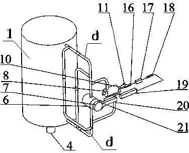
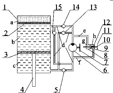
[0019] Such as figure 1 and figure 2 As shown, the shock absorber of the present invention includes a cylinder body 1 , a floating piston 2 , a piston 3 and a piston rod 4 . Both the floating piston 2 and the piston 3 are located in the cylinder body 1, and both are in sealing contact with the inner wall of the cylinder body 1, the floating piston 2 is above the piston 3, and the floating piston 2 and the piston 3 divide the cylinder body 1 into the upper compressed air chamber a, The upper oil chamber b in the middle and the lower oil chamber c in the lower part. The piston rod 4 is connected with the piston 3 and protrudes from the lower end of the cylinder body 1 . The compressed air chamber a can effectively reduce the high-frequency vibration generated when the wheel receives a sudden impact, and compensate the reduction of the oil storage volume of the cylinder 1 caused by the piston rod 4 entering the cylinder 1 . Outside the cylinder body 1, the oil between the upp...


PUM


Abstract

The invention provides a hydraulic damper with actively-adjustable damping. A hydraulic motor which is fixedly connected with a flywheel is arranged on a hydraulic loop outside a cylinder body. An upper pipeline of the hydraulic motor is connected with a left cylinder of double-effect hydraulic cylinders, and a lower pipeline of the hydraulic motor is connected with a right cylinder of the double-effect hydraulic cylinders. Pistons are arranged in cylinder bodies of the double-effect hydraulic cylinders. A pushing rod which extends out of the right cylinder is connected with a variable resistance rod. One end of a variable resistor is connected with a positive electrode of a power supply, and the other end of the variable resistor is connected with a coil wound on a second electromagnet. A negative electrode of the power supply is connected with a coil wound on a first electromagnet through a protective resistor. Electrifying directions on the coils on the two electromagnets are opposite. One end of the second electromagnet is connected with a friction shoe which is attached with the flywheel. Pressure difference between the two ends of the hydraulic motor is used for pushing the pistons, the pushing rod changes the magnitude of variable damping connected into a circuit, so that currents are changed, repulsive force between the two electromagnets is changed along with the currents, and accordingly friction force between the friction shoe and the flywheel is changed, and finally resistance of the hydraulic motor on pipeline oil liquid is changed.

Description

technical field [0001] The invention relates to a shock absorber installed on an automobile, in particular to a hydraulic shock absorber with actively adjustable damping. Background technique [0002] The automobile shock absorber is installed between the frame and the axle to attenuate the vibration of the vehicle body. The working principle of the traditional shock absorber is: when the wheel of the car moves upwards and approaches the frame, the shock absorber is compressed, the piston rod moves down, the oil pressure in the lower oil chamber rises, and the flow valve and compression valve are opened for unloading; when the wheel of the car When moving downwards away from the frame, the shock absorber recovers, the piston rod moves up, the oil pressure in the upper oil chamber increases, and the extension valve and compensation valve open for unloading. [0003] Traditional shock absorbers dissipate the vibration energy of a running vehicle directly in the form of heat ...

Claims


Application Information

Patent Timeline
Patent Type & Authority Applications(China)
IPC IPC(8): F16F9/512
Inventor 李仲兴陈望琚龙玉徐兴
Owner JIANGSU UNIV
Why Eureka
Try Eureka