An arc extinguishing chamber and a DC contactor using the arc extinguishing chamber

A DC contactor and arc-extinguishing chamber technology, applied in the field of arc-extinguishing chamber, can solve the problems of large loss of arc-extinguishing chamber, short life, long arc movement time, etc. Effect

Active Publication Date: 2017-02-08
ANDELI GRP
View PDF9 Cites 0 Cited by
  • Summary
  • Abstract
  • Description
  • Claims
  • Application Information

AI Technical Summary

Problems solved by technology

[0005] The technical problem to be solved by the present invention is that in the prior art, the electric arc moves in the arc extinguishing chamber for too long, especially when the current is too high, the high temperature of the arc causes large loss of the arc extinguishing chamber and short life. Quickly pull the arc to the maximum, timely and effectively extinguish the arc, safe and durable high-voltage and high-current DC contactor with integrated arc extinguishing device

Method used


Image

  • An arc extinguishing chamber and a DC contactor using the arc extinguishing chamber
  • An arc extinguishing chamber and a DC contactor using the arc extinguishing chamber
  • An arc extinguishing chamber and a DC contactor using the arc extinguishing chamber

Examples


Embodiment 1

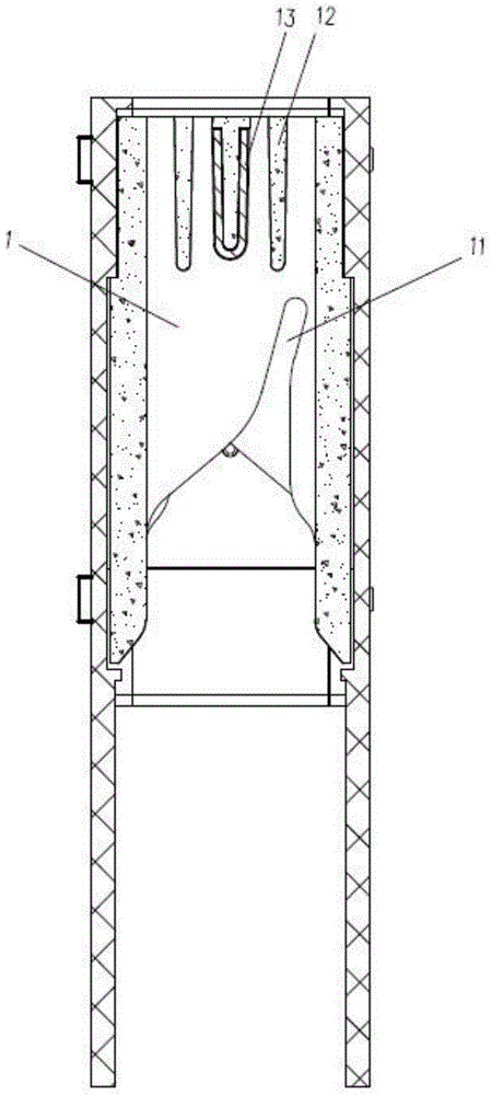
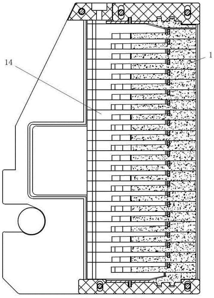
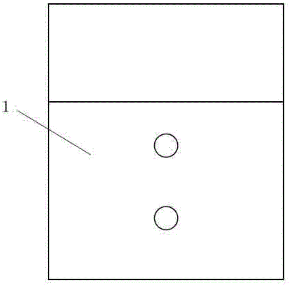
[0042] The structure of an arc extinguishing chamber according to the present invention is as follows: figure 2 As shown, in the arc extinguishing chamber 14, 26 arc extinguishing plates 1 are alternately arranged in layers. Except for the top arc extinguishing plate 1 and the bottom arc extinguishing plate 1, the arc extinguishing plate 1 in the middle position has an arc guide opening at one end. 11. The other end is provided with three arc extinguishing ribs 12 facing the arc extinguishing chamber 14 at intervals, and a bent and connected metal sheet 13 is arranged on the arc extinguishing rib 12 at the middle position. In this embodiment, the bent and connected The metal sheet 13 is U-shaped, and its opening direction faces the wall of the arc extinguishing chamber. The arc extinguishers 1 located at the top and bottom, in order to prevent arc leakage, are not provided with an arc guide port 11, and its structure is as follows Figure 3A with Figure 3B As shown, two pr...

Embodiment 2

[0046] On the basis of the arc extinguishing chamber 14 described in Embodiment 1, arc guide openings 11 are provided on the layered arc extinguishing plates 1 except for the top and bottom arc extinguishing plates 1 . The arc guide opening 11 is arranged on one side of the center line of the arc extinguishing plate 1 , and the positions of the arc guide openings 11 of two adjacent arc extinguishing plates 1 are staggered. In this embodiment, the arc guide opening 11 starts from one end of the arc extinguishing plate 1 and gradually shrinks to end at one side of the center line of the arc extinguishing plate 1 . exist Figure 5B As shown, as on one layer of arc extinguishing sheet 1, the arc guide port 11 gradually shrinks to the right side, then in the adjacent upper and lower layer of arc extinguishing sheet 1, as Figure 5A As shown, the arc guide openings 11 are gradually shrunk to the left side, so that the arc guide openings 11 on each layer of arc extinguishing plates ...

Embodiment 3

[0050] A DC contactor such as Figure 4 As shown, it includes a moving contact assembly 3 and a static contact assembly 5, an upwardly bent upper arc angle assembly 2 is arranged beside the moving contact of the moving contact assembly 3, and an Next to the static contact is a downwardly bent lower arc-guiding angle assembly 6, and an arc-extinguishing chamber 14 is arranged between the upper arc-guiding angle assembly 2 and the lower arc-guiding angle assembly 6, and the upper and lower arc-guiding angles The assembly 6 can guide the arc more quickly and stably into the arc extinguishing chamber 14, avoiding the free movement of the arc to damage other structures in the contactor; the arc extinguishing chamber 14 is alternately arranged with 26 pieces of arc extinguishing plates 1, such as figure 2 As shown, in addition to the top arc extinguishing plate 1 and the bottom arc extinguishing plate 1, the arc extinguishing plate 1 in the middle position has an arc guide port 11 ...


PUM


Abstract

The invention relates to an arc extinguish chamber and a direct current contactor adopting the arc extinguish chamber. The direct current contactor comprises a moving contact assembly and a stationary contact assembly, wherein an upper arc guide angle assembly bent upwards is arranged beside a moving contact of the moving contact assembly, a lower arc guide angle assembly bent downwards is arranged beside a stationary contact of the stationary contact assembly, the arc extinguish chamber is arranged between the upper arc guide angle assembly and the lower arc guide angle assembly, arc guide pieces are alternatively arranged in the arc extinguish chamber in a layering mode, an arc guide port is formed in one end of each arc extinguish piece, a plurality of arc extinguish ribs facing the interior of the arc extinguish chamber are arranged at the other end of each arc extinguish piece at intervals, and a metal piece connected in a bending mode is arranged at least on one arc extinguish rib. The arc extinguish chamber and the direct current contactor adopting the arc extinguish chamber resolve the problems in the prior art that the motion time of the electric arc in the arc extinguish chamber is too long, and the arc extinguish chamber is large in loss and short in service life under the conditions that currents are too strong or too weak, can rapidly pull the electric arc to the maximum, timely and effectively extinguishes the electric arc and is safe and durable.

Description

technical field [0001] The invention relates to a DC contactor, in particular to an arc extinguishing chamber and a DC contactor using the arc extinguishing chamber. Background technique [0002] With the development of my country's economy, DC power transmission and distribution in power systems and their control systems, such as the DC power supply of rail transit electric locomotives, and the DC power supply system in wind power generation have been widely used. The idea of ​​building a micro-grid and a DC distribution network has been proposed, but at present there is a lack of reliable DC electrical equipment, so it is imminent to develop new DC electrical equipment such as DC contactors, especially for high-voltage (1500V) high-current (800A) heavy The DC contactor for the task (DC5) is urgently needed. [0003] As we all know, in the process of breaking the fault current, normal working current and critical current, arcs are generated between the moving and static cont...

Claims


Application Information

Patent Timeline
Patent Type & Authority Patents(China)
IPC IPC(8): H01H9/34
Inventor 毛惠强陈武奇刘忠
Owner ANDELI GRP
Why Eureka
Try Eureka