Fluctuating wall cylinder experimental device

An experimental device and cylinder technology, applied in measurement devices, fluid dynamics tests, instruments, etc., can solve problems such as column wake vortex shedding, column fatigue damage, vortex-induced resonance, etc., and achieve the effect of low cost, stable and reliable operation

Inactive Publication Date: 2015-08-05
广西农垦昌菱农场有限公司
View PDF6 Cites 0 Cited by
  • Summary
  • Abstract
  • Description
  • Claims
  • Application Information

AI Technical Summary

Problems solved by technology

[0002] In inland river and marine engineering, there are many underwater cylindrical structures, such as offshore platform pillars, pier foundation columns, bridge piers, etc. The environmental loads on these underwater columns mainly include wind, wave, current, ice and seismic loads, etc. Among them, waves and water flow are the most important loads. At a certain flow rate, periodic vortex shedding will occur in the wake of the column. Especially when the natural frequency of the column is close to the frequency of vortex shedding, vortex induced resonance occurs. Cause fatigue damage to the column, seriously affect the service life and performance of the column, and even cause serious engineering and environmental accidents
[0003] At present, the influence of moving wave wall cylinder on vortex-induced vibration and resistance is still in the stage of theoretical research, and there is no experimental verification. A moving wave wall that can accurately simulate wave motion, adjust different parameters, and verify numerical simulation results is needed. The cylinder experimental device provides guidance and basis for practical engineering applications

Method used


Image

  • Fluctuating wall cylinder experimental device
  • Fluctuating wall cylinder experimental device
  • Fluctuating wall cylinder experimental device

Examples


Embodiment Construction

[0029] Further description will be given below in conjunction with the accompanying drawings and embodiments.

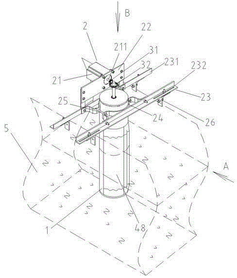
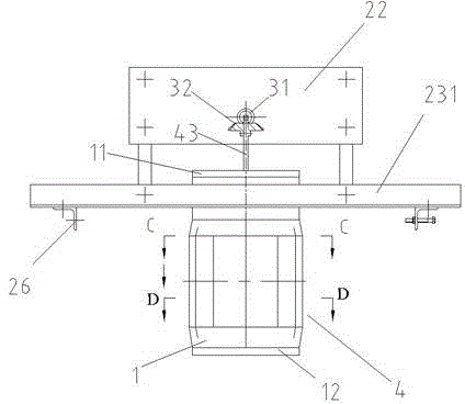
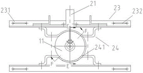
[0030] like Figure 1 to Figure 10 As shown, the present invention includes a cylinder 1, a power mechanism 2, a transmission mechanism 3 and a wave mechanism 4, the power mechanism 2 is arranged on the upper end of the cylinder 1, and the transmission mechanism 3 is vertically arranged in the cylinder 1, coaxially arranged with the transmission mechanism 3 The wave mechanism 4 is arranged in the cylinder 1, including the cylinder upper cover 11, the cylinder lower cover 12, two upper wave wheels 41, two lower wave wheels 42, an upper transmission shaft 43, a lower transmission shaft 44, a plurality of Ejector rod 45, multiple wave rods 46, return spring 47 and elastic skin 48 containing part of the cylinder, cylinder upper cover 11 and cylinder lower cover 12 are respectively fixed on the upper and lower ends of cylinder 1 through threaded connection, upload The mo...


PUM


Abstract

The invention discloses a moving wavy wall cylinder experimental apparatus comprising a cylinder, a power mechanism, a transmission mechanism, and a fluctuation mechanism. The power mechanism s disposed on the top of the cylinder. The transmission mechanism is vertically disposed inside the cylinder. The output end of the power mechanism is joined to the top of the transmission mechanism. The fluctuation mechanism arranged coaxial with the transmission mechanism is disposed inside the cylinder and is composed of two top fluctuation wheels, two bottom fluctuation wheels, a top transmission shaft, a bottom transmission shaft, multiple push rods, multiple fluctuation rods, and an elastic covering sheath. The top transmission shaft and the bottom transmission shaft are vertically disposed inside the cylinder. The outer contour lines of the top fluctuation wheels or the bottom fluctuation wheels are enclosed annular curves formed by peaks and valleys of continuous waveforms. The multiple push rods respectively pass through a corresponding push rod guiding hole on the wall of the cylinder. The multiple fluctuation rods are fixedly connected with the inner side surface of the elastic covering sheath. The moving wavy wall cylinder experimental apparatus achieves a purpose of simulating wave movement with the simple transmission mechanism and has low cost and steady and reliable operation.

Description

technical field [0001] The invention relates to an experimental device for studying the flow around a dynamic wave wall cylinder to obtain the suppression effect of the wave wall on vortex-induced vibration and resistance, and belongs to the technical field of inland river and ocean engineering simulation experiments. Background technique [0002] In inland river and marine engineering, there are many underwater cylindrical structures, such as offshore platform pillars, pier foundation columns, bridge piers, etc. The environmental loads on these underwater columns mainly include wind, wave, current, ice and seismic loads, etc. Among them, waves and water flow are the most important loads. At a certain flow rate, periodic vortex shedding will occur in the wake of the column. Especially when the natural frequency of the column is close to the frequency of vortex shedding, vortex induced resonance occurs. It will cause fatigue damage to the column, seriously affect the service...

Claims


Application Information

Patent Timeline
Patent Type & Authority Patents(China)
IPC IPC(8): G01M10/00
Inventor 王志东刘家欢窦京陈剑文吕红皊李力军吴娜凌宏杰
Owner 广西农垦昌菱农场有限公司
Why Eureka
Try Eureka