Parallel clamping device and method for robot end

A robot and parallel clamping technology, applied in the direction of chucks, manipulators, manufacturing tools, etc., can solve the problems of inconvenient maintenance, high equipment cost, poor automatic workpiece centering ability, etc., to improve production efficiency and degree of automation, centering High stability and synchronization, high clamping accuracy

Inactive Publication Date: 2014-03-19
GSK CNC EQUIP
View PDF8 Cites 10 Cited by
  • Summary
  • Abstract
  • Description
  • Claims
  • Application Information

AI Technical Summary

Problems solved by technology

However, in practical applications, the way of pneumatic parallel grippers is to use the pneumatic system of the production line to directly control the movement of parallel grippers. This method has complex equipment structure, small clamping force, inconvenient maintenance, and high equipment cost; The way the cylinder controls the grippers is to set up two sets of cylinder mechanisms to control the grippers that make up the parallel grippers separately. However, in actual production, the parallel grippers have poor synchronization and ri

Method used


Image

  • Parallel clamping device and method for robot end
  • Parallel clamping device and method for robot end
  • Parallel clamping device and method for robot end

Examples


Embodiment

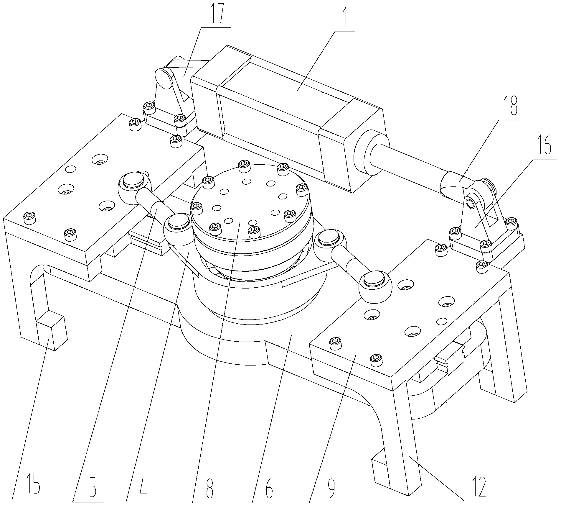
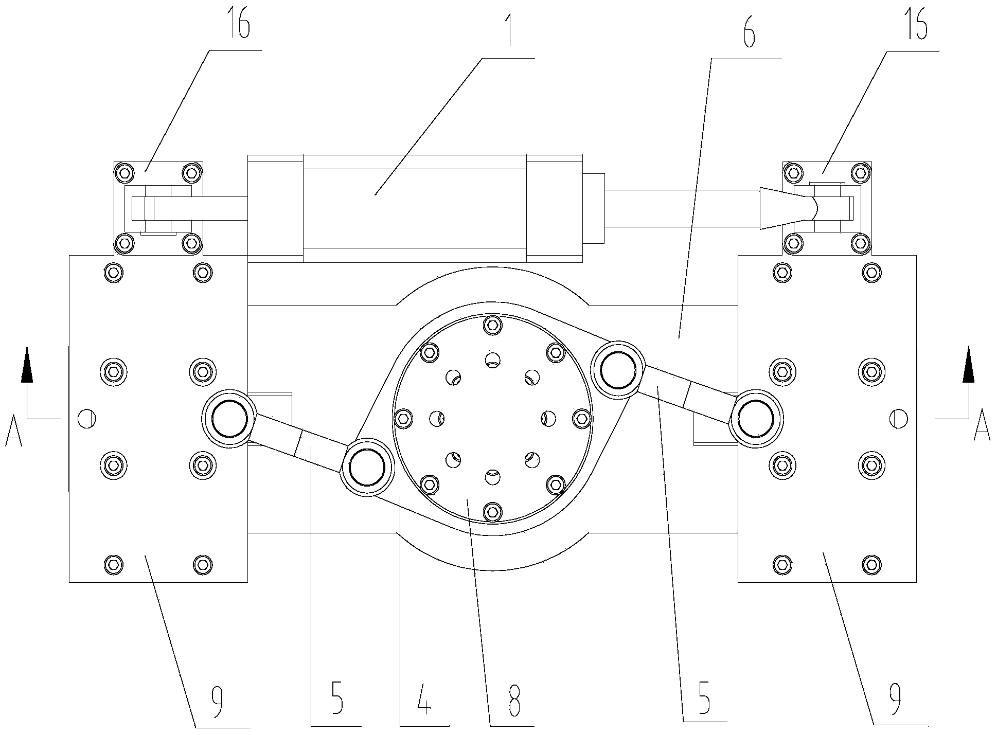
[0028] In this embodiment, a parallel clamping device for the end of the robot, such as figure 1 or figure 2 As shown, it includes driving cylinder 1, parallel clamping mechanism and two sets of end clamping mechanisms. The two sets of end clamping mechanisms are respectively arranged on both sides of the parallel clamping mechanism. connect.

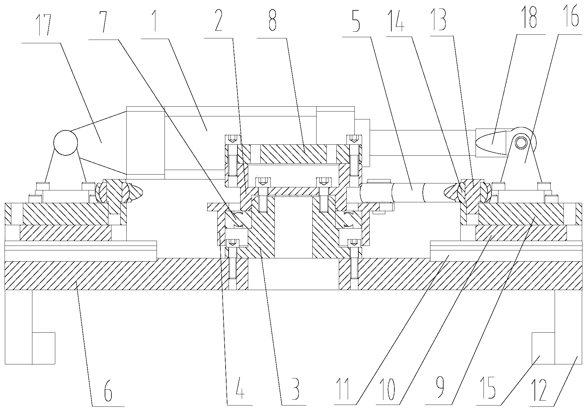
[0029] Such as image 3 As shown, the parallel clamping mechanism includes a compression flange 2, a central shaft 3, a rotating seat 4, an adjustment rod 5, and an adjustment base plate 6. The compression flange is fixedly connected to the top of the central shaft, and the bottom of the central shaft is fixedly connected to the adjustment base plate. The swivel seat is connected with the outer periphery of the central shaft through the central bearing 7, the bottom of the compression flange is pressed against the inner ring of the central bearing, and the top surface of the swivel seat is connected with the terminal clamping mechani...


PUM


Abstract

The invention discloses a parallel clamping device and method for a robot end. The parallel clamping device for the robot end comprises a driving air cylinder, a parallel clamping mechanism and two end clamping mechanisms, wherein the two end clamping mechanisms are arranged on the two sides of the parallel clamping mechanism respectively, and the two ends of the driving air cylinder are fixedly connected with the two end clamping mechanisms respectively. The parallel clamping method for the robot end comprises the steps that the two end clamping mechanisms are symmetrically arranged on the two sides of the parallel clamping mechanism respectively, and are connected with the parallel clamping mechanism through adjusting rods, the two ends of each adjusting rod are hinged to the parallel clamping mechanism and the corresponding end clamping mechanism, a rotating base is used in cooperation so that when the driving air cylinder works, the two end clamping mechanisms can be driven to synchronously run, and clamping or loosening of workpieces can be achieved. According to the parallel clamping device for the robot end, the mode that one driving air cylinder is used for driving the two end clamping mechanisms is adopted, the rotating base and the adjusting rods are used in cooperation, synchronous operation of the two end clamping mechanisms is achieved, clamping is stable, alignment performance and synchronism are high, the accuracy rate of clamping is high, and production efficiency and the degree of automation of a production line can be effectively improved.

Description

technical field [0001] The invention relates to the technical field of industrial robots for automatic handling, in particular to a parallel clamping device and method for the end of a robot. Background technique [0002] In robot automatic handling technology, the clamping method of two-finger parallel motion is widely used, and this clamping method can be used for plate parts, disk parts, shaft parts, box parts, etc. [0003] At present, there are two main two-finger gripping methods used at home and abroad: one is to directly use pneumatic parallel grippers, and the other is to use dual cylinders to control parallel grippers. However, in practical applications, the way of pneumatic parallel grippers is to use the pneumatic system of the production line to directly control the movement of parallel grippers. This method has complex equipment structure, small clamping force, inconvenient maintenance, and high equipment cost; The way the cylinder controls the grippers is to ...

Claims


Application Information

Patent Timeline
IPC IPC(8): B25J15/08
Inventor 关天俊周长顺陈其忠
Owner GSK CNC EQUIP
Why Eureka
Try Eureka