Touch module and operating method thereof

A touch module, touch point technology, used in instruments, electrical digital data processing, input/output process of data processing, etc.

Inactive Publication Date: 2014-05-14
CORETRONIC
View PDF9 Cites 9 Cited by
  • Summary
  • Abstract
  • Description
  • Claims
  • Application Information

AI Technical Summary

Problems solved by technology

[0004] Due to the good collimation of the laser and the small focused spot, some optical touch panels use laser light sources, but the laser is also easy to cause strong damage to the retina and skin of the human eye

Method used


Image

  • Touch module and operating method thereof
  • Touch module and operating method thereof
  • Touch module and operating method thereof

Examples


Embodiment Construction

[0017] The foregoing and other technical contents, features and effects of the present invention will be clearly presented in the following detailed descriptions of multiple embodiments in conjunction with the accompanying drawings. The directional terms mentioned in the following embodiments, such as "upper", "lower", "front", "rear", "left", "right", etc., are only referring to the directions of the drawings. Accordingly, the directional terms are used to illustrate, not to limit, the invention.

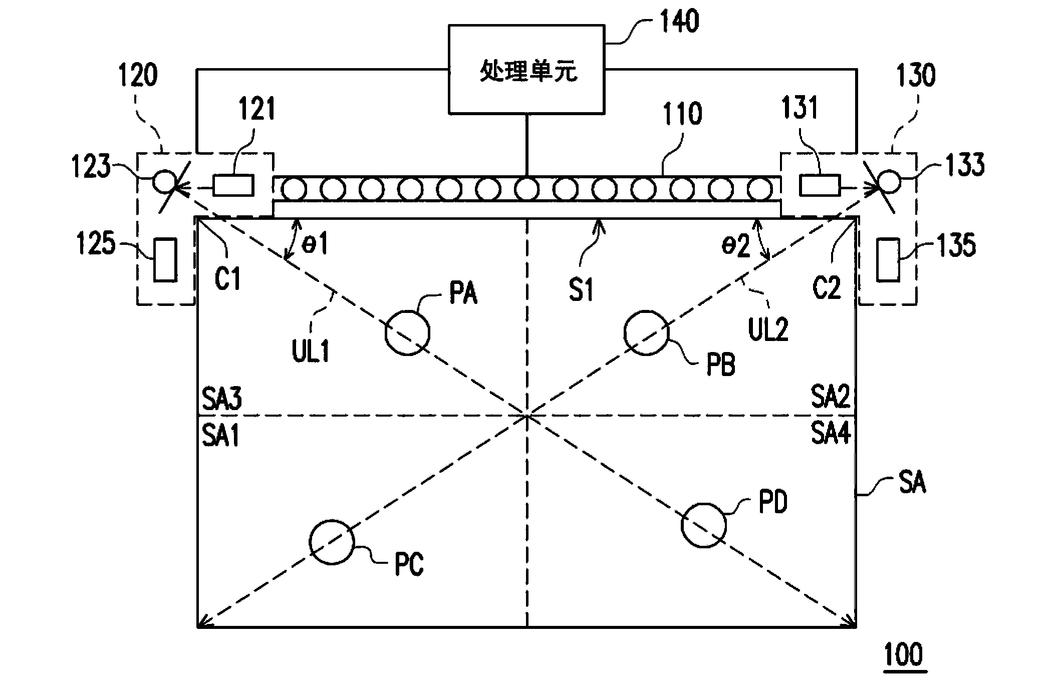
[0018] figure 1 It is a system diagram of a touch module according to an embodiment of the present invention. refer to figure 1 , in this embodiment, the touch module 100 includes a photosensitive semiconductor array 110 , a first photosensor 120 , a second photosensor 130 and a processing unit 140 . Moreover, the processing unit 140 is coupled to the photosensitive semiconductor array 110 , the first light sensor 120 and the second light sensor 130 . The photosensitive semicon...


PUM


Abstract

The invention provides a touch module and an operating method thereof. The operating method includes the steps of detecting a touch point and judging whether the touch point is under normal touch or not according to results of detecting the touch point; if not, decreasing the intensity of infrared laser of the touch module; if yes, judging the position of the touch point. Therefore, damage caused by the infrared laser to human vulnerable parts during abnormal touch can be decreased or avoided.

Description

technical field [0001] The present invention relates to a touch module and its operation method, and in particular to an infrared laser touch module and its operation method. Background technique [0002] The touch technology simplifies the communication of the man-machine interface, and the user can control the electronic device by finger touch to perform corresponding operations. Touch panels can be roughly classified into resistive touch panels, capacitive touch panels, optical touch panels, acoustic touch panels, and electromagnetic touch panels. Since the touch mechanism of the optical touch panel is suitable for large-size display panels, the touch function of the large-size display panel is mostly achieved through the optical touch mechanism. [0003] In terms of optical scanning touch technology, the main components include light source, micro-mechanical lens, photosensitive IC and photosensitive semiconductor array. The light emitted by the light source is reflect...

Claims


Application Information

Patent Timeline
Patent Type & Authority Applications(China)
IPC IPC(8): G06F3/042
CPCG06F3/0423
Inventor 张根荣蔡文玮梁国原
Owner CORETRONIC
Why Eureka
Try Eureka