Fingerprint collection system and fingerprint information collection method

A fingerprint collection and fingerprint technology, applied in instruments, character and pattern recognition, computer parts and other directions, can solve the problems of a single fingerprint detection method, affect fingerprint recognition, complex manufacturing process, etc., achieve good collection and recognition effect, improve system Safety, the effect of rejecting fake finger deception

Active Publication Date: 2014-05-21
成都费恩格尔微电子技术有限公司 +1
View PDF7 Cites 60 Cited by
  • Summary
  • Abstract
  • Description
  • Claims
  • Application Information

AI Technical Summary

Problems solved by technology

[0004] Most of the existing fingerprint sensors use pure capacitive fingerprint sensors, and the fingerprint residues and other dirt residues have a relatively large impact, which seriously affects the recognition of fingerprints.
For example, a technical solution in the prior art provides a capacitive fingerprint reading method, in which the insulating layer between the direct contact surface of the finger and the sensing electrodes of the sensing array is made of an inorganic compound with a thickness of only a few um Composition, resulting in extremely poor hydrophobicity, residue resistance, pressure resistance and antistatic properties
Among the existing foreign fingerprint sensors, only two companies, AUTHENTEC and FPC, have realized radio frequency fingerprint collection, and the radio frequency collection principles of the two companies are basically the same, and radio frequency fingerprint collection can be very good against fingerprint residue and other pollution quality residue, but in some applications with strong radio frequency radiation, its anti-interference ability is poor, so the application range is limited
[0005] like figure 1 As shown, a fingerprint collection system in the prior art, its sensing unit 10 includes: a sensing capacitor 11, formed by the finger 1 and the sensing electrodes; a fringe capacitor 12, formed by the sensing electrodes and the output of the amplifier 13 Electrodes are formed; an amplifier 13, an input end is connected between the sensing capacitor 11 and the fringe capacitor 12, an input end is grounded, and an output end is connected to the other end of the fringe capacitor 12; The radio frequency signal reflected by the finger 1 is processed by the subsequent circuit (not shown) after passing through the capacitance integral amplification circuit, and the radio frequency signal with different amplitudes is detected according to the different sensing capacitance values, thereby realizing fingerprint collection. Each sensing unit 10 uses an amplifier 13, and the process deviation between the amplifiers is difficult to correct, which increases the complexity of the circuit implementation, and a radio frequency pulse signal of the system corresponds to one pixel or multiple pixel information, and radio frequency radiation interference Stronger places are more susceptible to interference
[0006] The above-mentioned existing fingerprint sensors, whether capacitive or radio-frequency, are single-mode fingerprint detection methods, cannot be flexibly applied in different places, and cannot well reject special fake finger models. cheat
If the fake finger model is plated with a layer of conductive material or semi-conductive material and it is ensured that the depth of the fingerprint valley line of the model after the material is pressed is greater than 2um (the specific value is determined by the sensitivity of the sensor), this special The fake finger model can fool the detection of existing fingerprint sensors (although the manufacturing process of this fake finger model is quite complicated and its cost is very high, it does not rule out that people with ulterior motives use this special fake finger model to cheat the verification)

Method used


Image

  • Fingerprint collection system and fingerprint information collection method
  • Fingerprint collection system and fingerprint information collection method
  • Fingerprint collection system and fingerprint information collection method

Examples


Embodiment Construction

[0024] In the following detailed description, only preferred embodiments of the invention are described with reference to the accompanying drawings. However, it should be understood that various modifications can be made without departing from the idea of ​​the present invention.

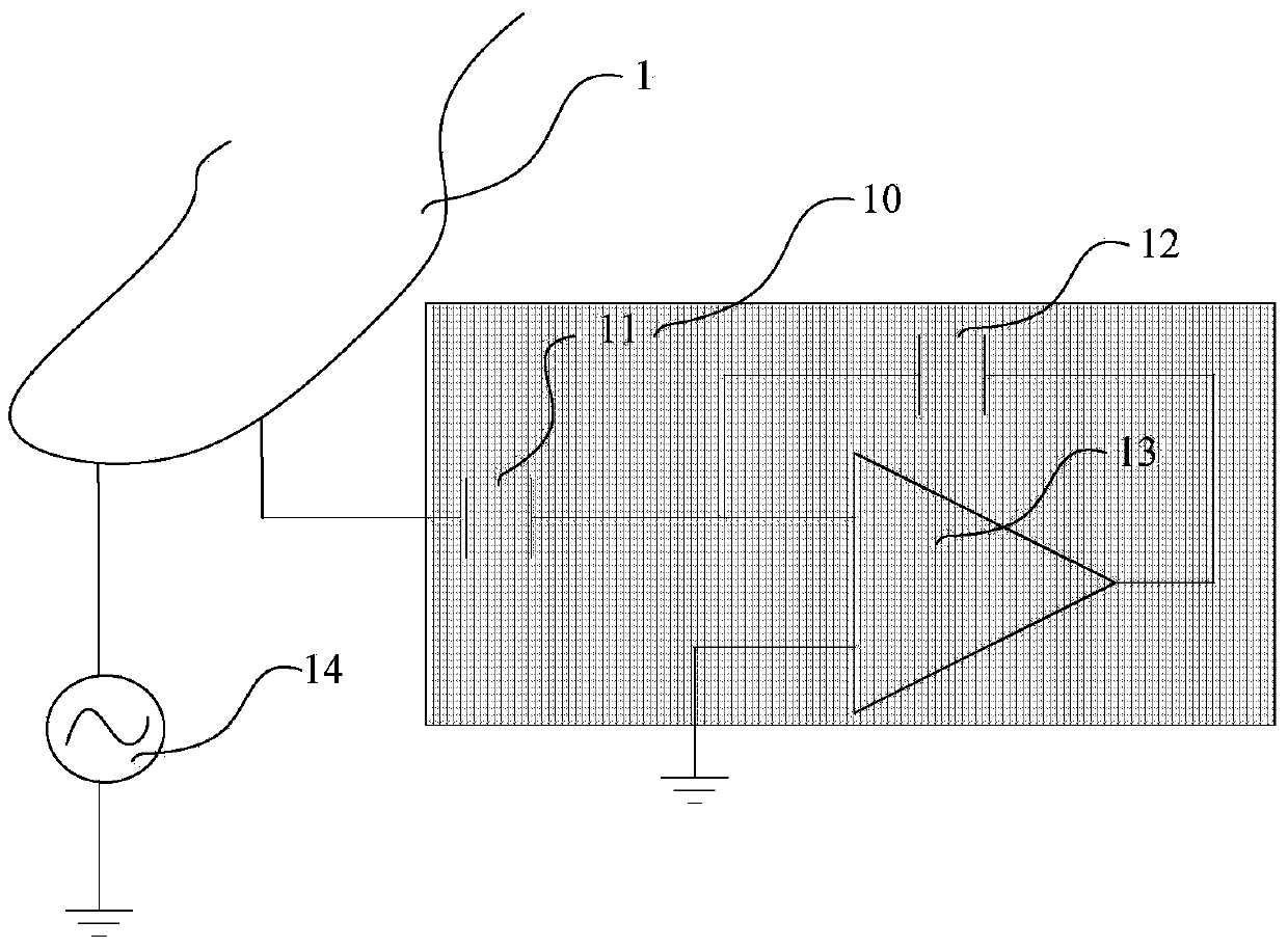
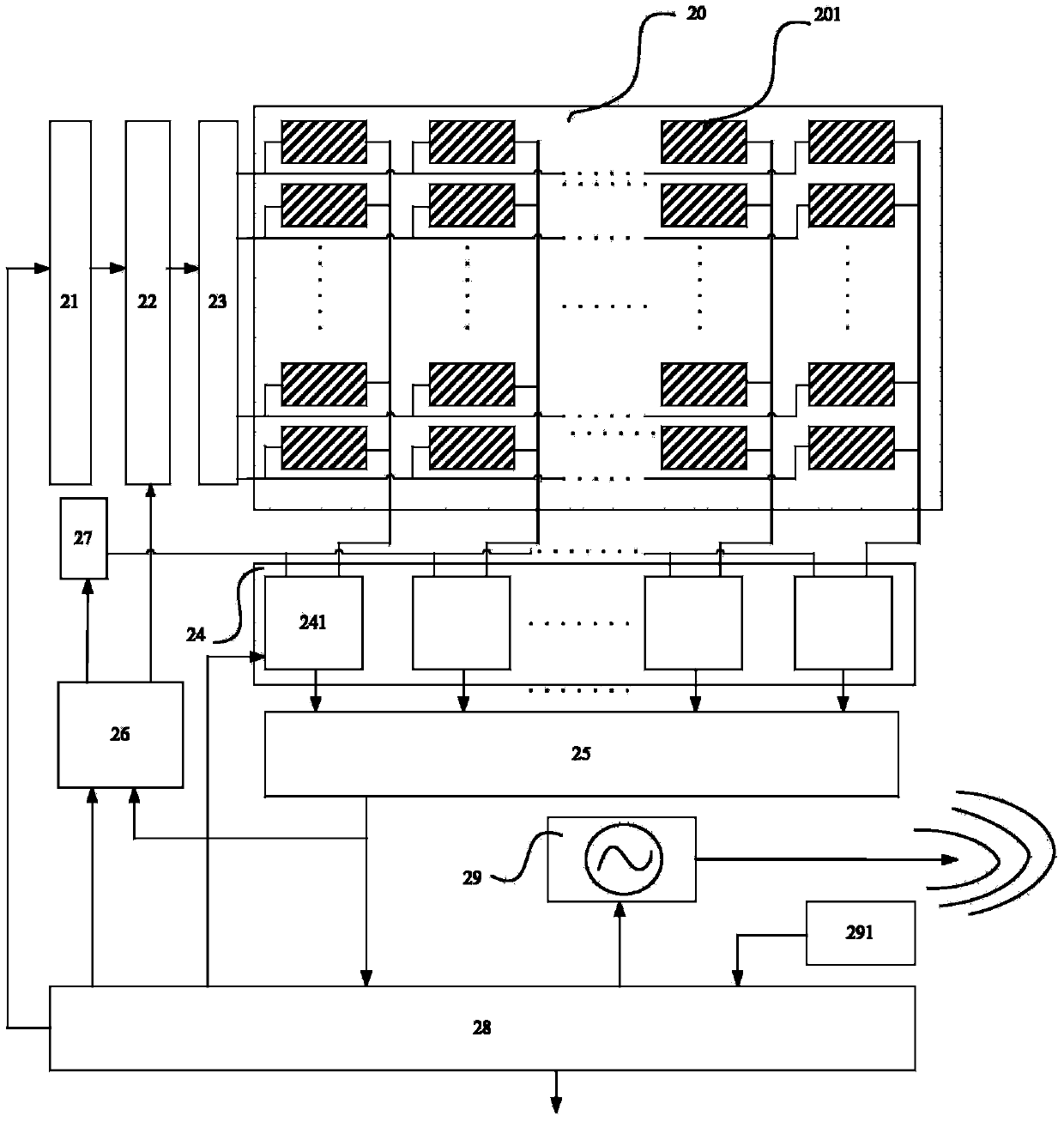
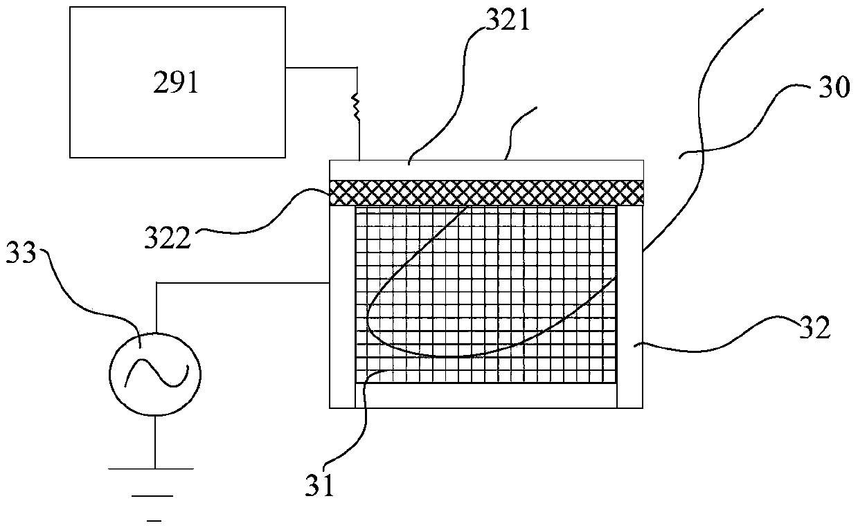
[0025] Such as figure 2 As shown, an embodiment of the present invention provides a fingerprint collection system, which is formed on a chip structure, and the chip includes: a fingerprint sensor, a mode control circuit 21, a scan controller 22, a sensing unit drive circuit 23 and an image output unit. Wherein, the fingerprint sensor includes a fingerprint sensing unit array 20, an antenna metal frame ( figure 2 not shown in ) and radio frequency driving circuit 29, fingerprint sensing unit array 20 includes a plurality of sensing units 201, radio frequency driving circuit 29 drives the antenna metal frame to emit radio frequency signals; scan controller 22 selects the fingerprint sensing unit a...


PUM


Abstract

The invention relates to a fingerprint collection system comprising a fingerprint sensor, a scanning controller, a sensing unit driving circuit, an image output unit and a mode control circuit. The fingerprint sensor comprises a fingerprint sensing unit array, an antenna metal frame and a radiofrequency driving circuit; the fingerprint sensing unit array includes multiple sensing units, and the radiofrequency driving circuit drives the antenna metal frame to transmit radiofrequency signals. The scanning controller is used for selecting at least part of the sensing units of the fingerprint sensing unit array to serve as effective sensing units for sensing fingerprints and converting the same into electric signals. The sensing unit driving circuit is used for providing time-sequence signals needed for work of the effective sensing units. The image output unit is used for converting electric signals into digital fingerprint image information and outputting the information. The mode control circuit is used for controlling the sensing unit driving circuit to send different time-sequence signals to change working modes of the fingerprint collection system. The working modes at least include a capacitive collection mode and a radiofrequency collection mode. The fingerprint collection system has wide application range and has good collection and recognition effects in various application fields.

Description

technical field [0001] The invention relates to the technical field of fingerprint collection. In particular, the present invention relates to a fingerprint collection system and a fingerprint information collection method. Background technique [0002] As people's requirements for information security are getting higher and higher, living biometric authentication and identification are more and more used in people's daily life. Fingerprint authentication has high reliability and cost-effectiveness in biometric authentication, and has become the mainstream of current biometric authentication. At the same time, fingerprint acquisition technology is also developing rapidly, and fingerprint sensors with lower cost, smaller size, lower power consumption and high dynamic range will occupy a huge market. Therefore, fingerprint sensors with the above advantages have become the focus of current research. Among them, the capacitive fingerprint sensor has become one of the current m...

Claims


Application Information

Patent Timeline
Patent Type & Authority Applications(China)
IPC IPC(8): G06K9/00
Inventor 黄昊徐启波
Owner 成都费恩格尔微电子技术有限公司
Why Eureka
Try Eureka