Drainage water saving conversion device

A conversion device and nozzle technology, applied in water supply devices, indoor sanitary piping devices, buildings, etc., can solve problems such as affecting the appearance, inconvenience, and odor, and achieve the effect of convenient conversion, avoiding trouble, and avoiding odor.

Active Publication Date: 2016-03-30
王凤蕊
View PDF6 Cites 0 Cited by
  • Summary
  • Abstract
  • Description
  • Claims
  • Application Information

AI Technical Summary

Problems solved by technology

In order to realize this conversion, users need to frequently switch and connect the drainage pipes with different floor drains, which is not only inconvenient but also has too many floor drains on the ground, which will affect the appearance, and if the empty floor drain is not sealed in time, it will easily lead to odor return, etc. question

Method used


Image

  • Drainage water saving conversion device
  • Drainage water saving conversion device
  • Drainage water saving conversion device

Examples


Embodiment 1

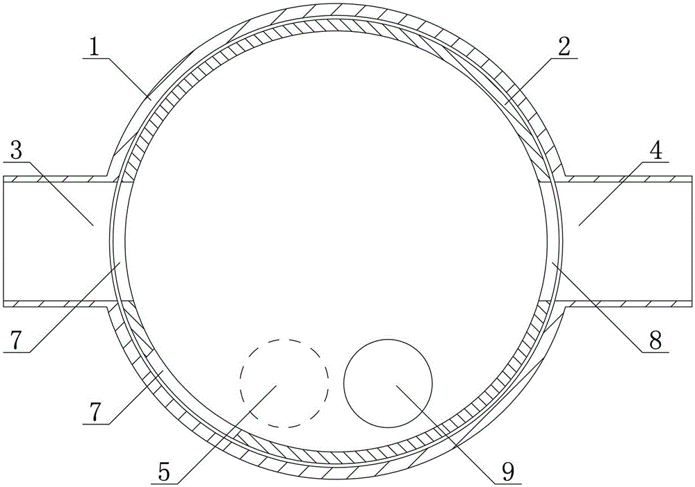
[0027] Such as figure 1 , figure 2 , image 3 As shown, a drainage and water-saving conversion device includes an outer valve cylinder 1 and an inner valve cylinder 2. The outer valve cylinder 1 is provided with an outer water inlet 3, a first outer water outlet 4 and a second outer water outlet 5. The inner valve cylinder 2 is provided with an inner water outlet 6 and an inner water inlet 7; the inner valve cylinder 2 is arranged in the outer valve cylinder 1 and is between the first position and the second position with the outer valve cylinder 1 Rotation fit: in the first position, the inner water outlet 6 is only in communication with the first outer water outlet 4, in the second position, the inner water outlet 6 is only in communication with the second outer water outlet 5, in In the first position and the second position, the inner water inlet is correspondingly communicated with the outer water inlet.

[0028] The specific working process is: connect the outer wate...

Embodiment 2

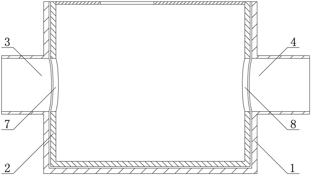
[0034] The difference between embodiment 2 and embodiment 1 is: as Figure 4 As shown, the first outer water outlet 4 and the second outer water outlet 5 are opened on the side wall of the outer valve cylinder 1, and the inner water outlet 6 is opened on the side wall of the inner valve cylinder 2 . In this design, only one inner water outlet is required on the inner valve cylinder 2, which reduces the number of inner water outlets, so that the connection with the first outer water outlet 4 can be realized through only one inner water outlet. and the communication between the second external water outlet 5.

Embodiment 3

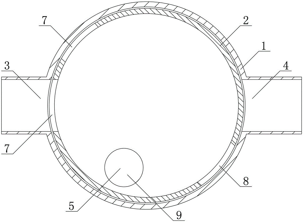
[0036] The difference between embodiment 3 and embodiment 1 is: as Figure 5As shown, the first outer water outlet 4 and the second outer water outlet 5 are opened on the bottom of the outer valve cylinder 1, and the inner water outlet 6 is opened on the bottom of the inner valve cylinder 2 . Similar to Embodiment 2, in this design, only one inner water outlet is required on the inner valve cylinder 2, and this design reduces the number of inner water outlets, so that only one inner water outlet can be used to communicate with all The communication between the first outer water outlet 4 and the second outer water outlet 5, and the outer water outlet is located at the bottom is easy for the water to flow downward under the action of gravity.


PUM


Abstract

The invention provides a drainage and water-saving conversion device, which comprises an outer valve cylinder and an inner valve cylinder, the outer valve cylinder is provided with an outer water inlet, a first outer water outlet and a second outer water outlet, and the inner valve cylinder is provided with An inner water inlet and an inner water outlet; the inner valve cylinder is arranged in the outer valve cylinder and rotates with the outer valve cylinder between the first position and the second position: in the first position, the inner outlet The water outlet is only connected to the first outer water outlet, and the inner water outlet is only connected to the second outer water outlet in the second position, and the inner water inlet is connected to the second outer water outlet in the first and second positions. The external water inlet is correspondingly connected. By rotating the inner valve cylinder, the direction of water flow is switched between the first outer water outlet and the second outer water outlet, so that the waste water flows to the water-saving tank or to the sewer, avoiding the trouble of directly switching the floor drain, easy to use, and When the second external water outlet is blocked, it is equivalent to blocking the floor drain, which effectively avoids the phenomenon of back odor.

Description

technical field [0001] The invention relates to a water flow conversion device, in particular to a drainage and water-saving conversion device for controlling the direction of water flow. Background technique [0002] At present, modular drainage and water-saving systems have been gradually promoted and popularized. However, due to the vastly different needs of residents, the working conditions of drainage water quality are also different. Some users want to drain certain part of waste water directly, and do not want to put it into the water-saving tank, such as the waste water containing a lot of detergent after the first washing of the washing machine; at the same time, they hope that some part of the water can be recycled into the water-saving tank , such as washing water with less detergent after washing in a washing machine. In order to realize this conversion, users need to frequently switch and connect the drainage pipes with different floor drains, which is not only...

Claims


Application Information

Patent Timeline
Patent Type & Authority Patents(China)
IPC IPC(8): E03C1/122E03C1/28E03C1/282
Inventor 王凤蕊李丽萍
Owner 王凤蕊
Why Eureka
Try Eureka