Single-phase electricity-saving appliance and control method thereof

A control method, single-phase section technology, applied in AC network to reduce harmonics/ripple, reactive power compensation, harmonic reduction devices, etc., can solve the problems of capacity waste, power factor reduction, harmonic content increase, etc., Achieve the effect of reducing manufacturing cost and saving power

Inactive Publication Date: 2014-06-04
李木
View PDF5 Cites 1 Cited by
  • Summary
  • Abstract
  • Description
  • Claims
  • Application Information

AI Technical Summary

Problems solved by technology

[0009] The above-mentioned first and second schemes of "cure the head for the headache and treat the foot for the foot pain" have not completely solved the problem of energy waste. It is often found that the harmonic content increases significantly when reactive power is compensated; the power factor is found to increase significantly when filtering. reduce
[0010] In the third scheme, the reactive power compensation device and the filtering device are independent of each other. At the beginning of the design, the historical operation data is often used for reference, and the maximum value of the reactive power consumption is taken as the minimum capacity of the reactive power compensation device; the maximum value of the harmonic power is used as the filtering device. The minimum capacity of the device, which makes the two independent energy-saving devices waste capacity for a long time, and the high combined cost makes users discouraged
The more serious situation is that the reactive power compensation device often injects harmonics into the filter device during operation, and the filter device produces reactive power consumption, etc., and the functions cancel each other out, which greatly reduces the overall power saving effect.

Method used


Image

  • Single-phase electricity-saving appliance and control method thereof
  • Single-phase electricity-saving appliance and control method thereof
  • Single-phase electricity-saving appliance and control method thereof

Examples


Embodiment Construction

[0027] The following examples belong to one of the specific forms of the present invention, and the purpose given is to describe the present invention in more detail, not to limit the scope of the present invention, nor to limit the application form of the present invention.

[0028] This example Figure 1 to Figure 4 shown.

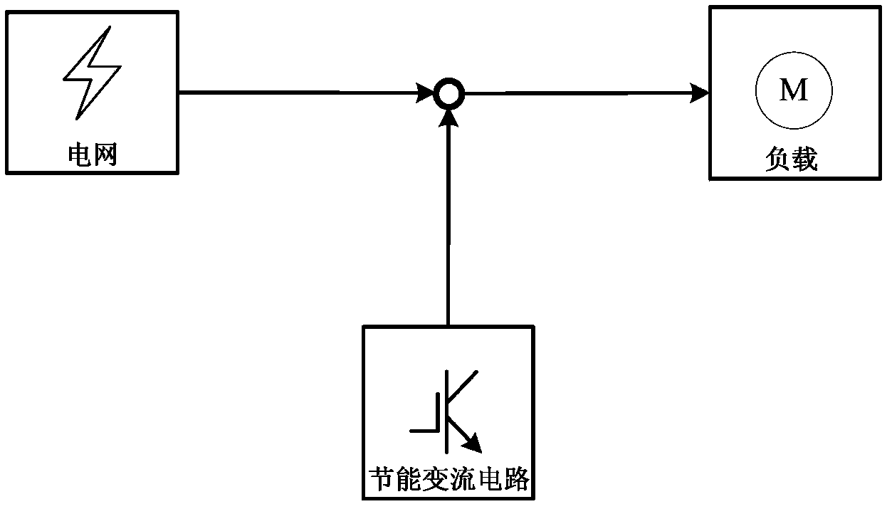
[0029] This embodiment includes a main control part, a power-saving converter circuit, and a detection circuit, and each component is electrically connected to each other, wherein the AC side of the power-saving converter circuit is directly electrically connected in parallel with the single-phase AC load. The schematic diagram of the electrical structure of the primary side of this embodiment is as follows figure 1 shown.

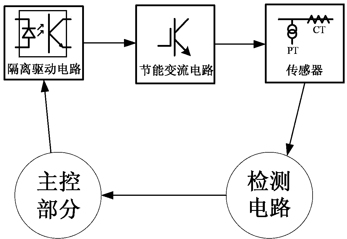
[0030] The detection circuit in this embodiment includes: a current sensor located between the parallel connection point of the power-saving converter circuit and the AC load and the grid, and a voltage sensor located between the l...


PUM


Abstract

The invention relates to an electricity-saving appliance, especially to a single-phase electricity-saving appliance having functions of static var generation and active filtering and a control method thereof. The single-phase electricity-saving appliance comprises a main control portion, an electricity-saving converter circuit, and a detection circuit; and all the components can be combined or split in the terms of function or structure and are connected respectively, mutually, and electrically. And an electricity-saving converter circuit alternating-current side and a single-phase alternating-current load are directly and electrically connected in parallel or indirectly and electrically connected in parallel by an isolation transformer. Besides, the control method includes the following steps that: the electricity-saving converter circuit detects a load side power parameter in real time and provides a matched reactive power; and meanwhile, a harmonic wave generated by the load is filtered. According to the invention, a power factor of a power transmission line can be improved; and the harmonic wave generated by the load can be filtered and the power quality can be optimized. Therefore, the energy loss can be reduced and an objective of electricity saving can be achieved.

Description

technical field [0001] The invention relates to a power saver, in particular to a single-phase power saver and a control method thereof. Background technique [0002] With the development of modern industry, the global demand for electric energy is increasing year by year, and the non-renewable resources that generate electric energy are frequently running out, and the price is also rising. Energy saving is an important issue for future generations. topic. [0003] Nowadays, there are a large number of inductive loads represented by electric motors among electric loads. When such loads are working, the grid must not only provide active power, but also must provide a certain amount of reactive power at the same time, which leads to grid-side power This situation greatly reduces the transmission efficiency of energy in the power grid, and because the load runs for a long time under the condition of high voltage and high current, it increases the loss of electric energy during...

Claims


Application Information

Patent Timeline
Patent Type & Authority Applications(China)
IPC IPC(8): H02J3/18H02J3/01
CPCY02E40/30Y02E40/40
Inventor 李木
Owner 李木
Why Eureka
Try Eureka