Clamping mechanism of line pipe welding edge

A technology of clamping mechanism and line pipe, which is applied in the direction of clamping device, clamping, metal processing machinery parts, etc., can solve the problems of loose clamping of pipe fittings, falling of pipe fittings, large interaction force, etc., and improve the clamping force , improve the service life and ensure the effect of efficiency

Inactive Publication Date: 2014-06-11
谭建新
View PDF6 Cites 13 Cited by
  • Summary
  • Abstract
  • Description
  • Claims
  • Application Information

AI Technical Summary

Problems solved by technology

[0003] However, in the actual beveling process, in order to improve the processing efficiency, the method of clamping and rotating cutting is usually used for tubular workpieces. However, when the cutting tool contacts the edge of the pipe during cutting, a large interaction force will be generated, making the pipe The clamping is prone to loosening, which will cause the pipe fittings to fall in severe cases, which will cause certain damage to the beveling machine or the edge of the pipe fittings

Method used


Image

  • Clamping mechanism of line pipe welding edge
  • Clamping mechanism of line pipe welding edge

Examples


Embodiment 1

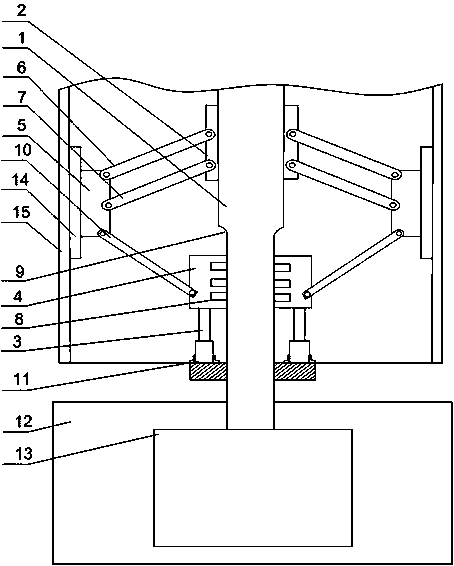
[0022] Such as figure 1 As shown, a pipe fitting 15 bevel processing device of the present invention includes a support frame 12, on which a fixed rod 1 and a drive motor 13 are arranged, and the output end of the drive motor 13 is connected to the bottom of the fixed rod 1, Fixed tube 2 and retaining ring 11 are installed on described fixed rod 1, also comprise cylinder 3, and cylinder 3 is fixed on the retaining ring 11, and the output end of described cylinder 3 is connected with fixed rod 1 through sliding cylinder 4, and sliding cylinder 4. It is arranged between the fixed cylinder 2 and the retaining ring 11. The two ends of the sliding cylinder 4 are hinged to the lower rod 10. The end of the lower rod 10 is hinged to the swing arm 5. The swing arm 5 passes through the upper swing rod 6 and the lower swing rod. 7 is hinged with the fixed cylinder 2, the two ends of the fixed rod 1 are provided with grooves 9, and a plurality of rollers 8 are installed in the sliding cyl...

Embodiment 2

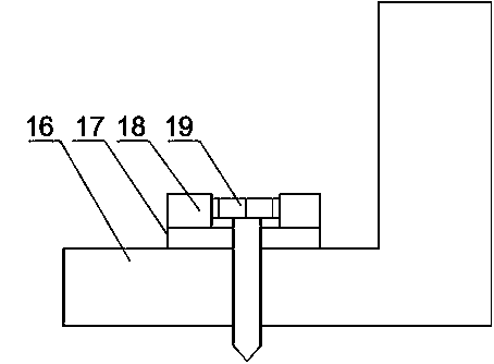
[0025] Such as figure 2 As shown, on the basis of Embodiment 1 in this embodiment, L-shaped baffles 16 are also installed at both ends of the cylinder 3, through holes are opened on the retaining ring 11 and the L-shaped baffle 16, and the retaining ring 11 The L-shaped baffle plate 16 is connected with the L-shaped baffle plate 16 through the through hole through the screw 19, and a washer 17 arranged on the through hole is also included, and an annular protrusion 18 is installed on the washer 17. The retaining ring 11 rotates together with the fixed rod 1, and the cylinder 3 will loosen during the non-stop rotation. The L-shaped baffle 16 clamps both ends of the cylinder 3, and the L-shaped baffle 16 and the retaining ring 11 are connected by screws 19. For connection, the annular protrusion 18 can well protect the screw 19 from external influences and improve the service life of the present invention.

Embodiment 3

[0027] Such as figure 1 As shown, in this embodiment, on the basis of Embodiment 1, the end face of the swing arm 5 away from the end of the fixed rod 1 is an arc surface; the arc surface is provided with a backing plate 14, and the arc of the backing plate 14 The surface area is greater than that of the arc surface of the swing arm 5; the roller 8 is a rubber wheel. When clamping the inner wall of the pipe fitting 15, the swing arm 5 is in contact with the inner wall of the pipe fitting 15, and the swing arm 5 on the arc surface can be completely attached to the inner wall of the pipe fitting 15, thereby improving the clamping force of the swing arm 5 on the pipe fitting 15; The backing plate 14 provided on the top can further increase the contact area with the inner wall of the pipe fitting 15 to ensure the stability of clamping.

[0028] Preferably, the rubber wheel can be deformed to a certain extent after the sliding cylinder 4 is subjected to stress, and the reaction fo...


PUM


Abstract

The invention discloses a clamping mechanism of a line pipe welding edge. The clamping mechanism comprises a support rack, wherein the support rack is provided with a fixed rod, which is provided with a fixed cylinder and a check ring, an air cylinder is fixed on the check ring, the output end of the air cylinder is connected with the fixed rod through a slide cylinder, the slide cylinder is arranged between the fixed cylinder and the check ring, pull-down rods are connected to two ends of the slide cylinder through hinges, swing arms are connected to the ends of the pull-down rods through hinges, the swing arms are hinged with the fixed cylinder through an upper swing rod and a lower swing rod, and when force of the swing arm applied to the inner wall of a pipe fitting reaches the maximum, a cutting tool on a lathe rotatably processes the edge of the pipe fitting, the adjustable swing arm can be used for processing grooves of pipe fittings with various diameters; the upper swing rod, the lower swing rod, the pull-down rods and the fixed rod form a triangular frame, and according to the principle of highest stability of the triangle, the swing arm can provide stable clamping force for the inner wall of the pipe fitting, and the high processing efficiency of the groove of the pipe fitting is guaranteed.

Description

technical field [0001] The invention relates to a profile cutting machine, in particular to a wire pipe welding edge clamping mechanism. Background technique [0002] The steel plate groove machine is used for deburring and groove processing of metal plates before welding. This machine mainly uses the principle of rolling washing to wash and cut the edge of the steel plate according to the required angle to obtain the groove required for welding. It is suitable for steel , cast iron, hard plastics, non-ferrous metals and other materials. The beveling machine is a special tool for chamfering and beveling pipes or flat plates on the front end of welding. Simple, standard angle, smooth surface and so on. The beveling machine has a variety of specifications, and it is an advanced tool provided for professional installation, maintenance and other work in industries such as electric power, petroleum, chemical industry, shipbuilding, and steel structure. This tool can greatly imp...

Claims


Application Information

Patent Timeline
Patent Type & Authority Applications(China)
IPC IPC(8): B23Q3/00
CPCB23Q3/00B23Q2703/10
Inventor 陈怀之王刚聂海涛张仁友胡国波
Owner 谭建新
Why Eureka
Try Eureka