

A Tunnel Model Test Method with Controllable Variation of Segment Joint Stiffness
A technology for segment joints and tunnel models, which is applied in tunnels, earth-moving drilling, mining equipment, etc., can solve problems such as changes, inability to provide accurate and reliable test basis for tunnel engineering design, construction and maintenance, and low reliability. To achieve the effect of accurate test data
Active Publication Date: 2016-04-20
SOUTHWEST JIAOTONG UNIV
View PDF6 Cites 0 Cited by
- Summary
- Abstract
- Description
- Claims
- Application Information
AI Technical Summary
Problems solved by technology
However, since the depth of the cutting groove cannot be changed with the load and other factors in the test, it cannot truly reflect the change of the mechanical properties of the segment joint during tunnel excavation and operation
[0006] However, the stiffness of segment joints in actual engineering changes with changes in the external environment such as loads. Therefore, the simulation of joint stiffness in the above method can only be aimed at a specific stress state of segment joints. The mechanical properties such as stiffness cannot be changed with other factors such as load during the test, which is inconsistent with the mechanical behavior of the tunnel joint in the actual project, resulting in large errors and low reliability in the test results of these model test methods, which cannot be used for the design of tunnel projects. , Construction and maintenance provide accurate and reliable test basis
At the same time, due to the fixed stiffness of the segment joints, the existing joint simulation methods cannot study the influence of the segment joint stiffness on the overall deformation and stress state of the tunnel structure
Method used
View moreImage
Smart ImageViewing Examples

Examples
Embodiment
[0024] figure 1 It is shown that a specific embodiment of the present invention is a tunnel model test method with controllable variation of segment joint stiffness, the method of which is:
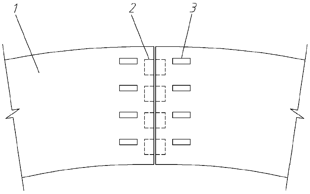
[0025] A. Make a model Make a separate model tunnel segment 1, and pre-embed an electromagnet 2 at the joint end of the model tunnel segment 1, and use a mold to align the model tunnel segment 1 into a model tunnel;
[0026] B. Instrument layout and initialization Arrange strain gauges 3 or displacement gauges on the side of the joint end of the model tunnel segment 1; pass a set initial current to the electromagnet 2, so that the magnetic force of the electromagnet simulates the initial stiffness of the joint between the segments;
Login to View More PUM
 Abstract
The invention relates to a test method for a tunnel model with duct piece connectors with rigidity in controllable changes. The method comprises the following steps: (A) making a model: embedding an electromagnetic iron (2) at the connector end of a model tunnel duct piece (1); (B) arranging and initialization of instruments: arranging strain gauges (3) or displacement meters on the side surface of the connector end of the model tunnel duct piece (1), and energizing a set initial current to the electromagnetic iron (2) so that the magnetic force of the electromagnetic iron simulates the initial rigidity of the connector; (C) loading test: calculating the current calculating value of the corresponding electromagnetic iron according to the load of each stage and the measured displacement value, changing the current value of the electromagnetic iron during loading of the next stage into the current calculating value, and simulating the rigidity of the duct piece connector of each stage. When the method is used for testing, the rigidity of the duct piece connector can be correspondingly changed along with the change of the load, which better conforms to the mechanical behavior of the tunnel duct piece connector in actual projects; the test data are more accurate and reliable, and an accurate and reliable test basis can be provided for the design, the construction and the maintenance of tunnel projects.
Description
technical field [0001] The invention relates to a tunnel model test method with controllable variation of segment joint stiffness. Background technique [0002] In tunnel engineering, the actual engineering and structural prototypes are generally large and complex, and their mechanical properties and stress mechanism cannot be obtained through direct research on the structure. Instead, model tests must be used, that is, with the help of models, tests are carried out according to the similarity principle and similarity criterion, so as to obtain various data and performance of the structure, and provide test basis for the design and construction of the tunnel. Shield tunnels are spliced by segments, and there are joints between the segments. There are many ways to connect the segment joints, such as bolted joints, joints without connectors, plug-in joints, and pin-insert joints. Due to its structural characteristics, the role of segment joints in the entire structure is ve...
Claims
Login to View More Application Information
Patent Timeline
 Patent Type & AuthorityPatents(China)
IPC IPC(8): E21D9/00
Inventor封坤何川齐春王均勇郭思良代聪
OwnerSOUTHWEST JIAOTONG UNIV