Motor rotor position and angle obtaining method

A technology of motor rotor and position angle, applied in the direction of electronic commutator, etc., can solve the problems of reduced motor speed regulation performance, motor phase current distortion, and different debugging results, and achieve low efficiency, low cost, and convenient operation Effect

Inactive Publication Date: 2014-10-01
NANJING UNIV OF AERONAUTICS & ASTRONAUTICS +1
View PDF4 Cites 21 Cited by
  • Summary
  • Abstract
  • Description
  • Claims
  • Application Information

AI Technical Summary

Problems solved by technology

Using the Hall sensor to detect the rotor position is to install the Hall sensor on the stator of the motor. However, the assembly error of the Hall rotor position sensor (there is no installation error for a single Hall) will cause the actual rotor position of the motor to be different from that passed through the Hall sensor. There is an error between the rotor positions detected by the sensor. The existence of this detection error will cause the estimated electrical angle waveform to be not an ideal sawtooth wave. Using this electrical angle to participate in the calculation of the drive signal will cause the motor phase current distortion and reduce the motor The speed regulation performance
[0004] At present, the detection of the installation error of the Hall-type motor rotor position sensor usually uses the method of manual experiment to adjust the installation position of the Hall position sensor. This method is limited by the experience of the debugging personnel, resulting in different debugging results. The whole process is inefficient and time-consuming.

Method used


Image

  • Motor rotor position and angle obtaining method
  • Motor rotor position and angle obtaining method
  • Motor rotor position and angle obtaining method

Examples


Embodiment Construction

[0029] The specific implementation manners of the present invention will be further described in detail below in conjunction with the accompanying drawings.

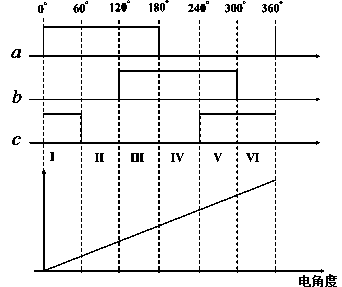
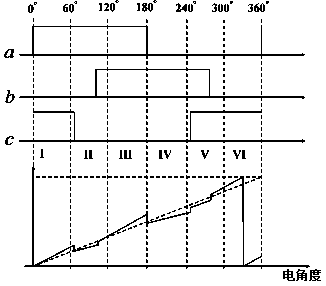
[0030] For the position angle of the motor rotor, three Hall rotor position sensors a, b and c installed on the motor stator are used to obtain the position angle, as shown in figure 1 shown, but in practical applications, A, B, and C are the coordinate systems corresponding to the three-phase stator windings, and the assembly error of the Hall rotor position sensor during installation (there is no installation error for a single Hall rotor position sensor) will cause the motor There is an error between the actual position of the rotor and the position of the motor rotor detected by the Hall rotor position sensor, so we have designed a method for obtaining the position angle of the motor rotor that corrects for this error.

[0031] For three Hall rotor position sensors installed on the motor stator, such as figure 1 As ...


PUM


Abstract

The invention relates to a motor rotor position and angle obtaining method. According to the method, an installation error of a Hall rotor position sensor on a motor stator is corrected, the structure is simple, thinking is clear, operation is convenient, the real-time position and angle of a motor rotor can be accurately obtained, the problems that an existing Hall rotor position sensor installation error detection method is low in efficiency, complex in engineering realization and the like are solved, the cost is low, practicability is high, the using effect is good, and use and popularization are facilitated.

Description

technical field [0001] The invention relates to a method for obtaining the position angle of a motor rotor. Background technique [0002] In the field of motor control technology, in order to realize the precise positioning of the servo motor and the three closed-loop control of position, speed and current, it is often necessary to know the position or speed information of the motor rotor, which can be obtained by installing a rotor position detector. Generally, the rotor position detector includes sensor devices such as photoelectric encoder disc, resolver, inductive synchronizer, linear Hall, switch Hall, etc. In addition to switch-type Hall sensors, other position detectors have high detection accuracy, but are expensive, and are not suitable for the field of motion control with high cost requirements. [0003] In order to expand the application of motors in low-cost electric drive systems, a switch-type Hall sensor with a small size, no contact, easy installation, and a...

Claims


Application Information

Patent Timeline
Patent Type & Authority Applications(China)
IPC IPC(8): H02P6/16
Inventor 秦海鸿荀倩聂新曾庆喜李寒松唐靖陆新芳李玉俊
Owner NANJING UNIV OF AERONAUTICS & ASTRONAUTICS
Why Eureka
Try Eureka