
Underwater manned testing door special for cleaning slot of steel gate of hydropower station
A technology for hydropower stations and test doors, which is applied in hydropower stations, hydroelectric power generation, underwater operation equipment, etc., to achieve the effects of stable water entry and exit, convenient installation, and small vibration
- Summary
- Abstract
- Description
- Claims
- Application Information
AI Technical Summary
Problems solved by technology
Method used
Image

Examples
Embodiment
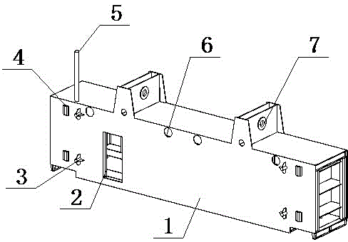
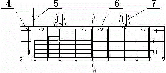
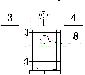
[0025] Such as figure 1 , 2 , shown in 3 and 4, a kind of underwater people's test door specially used for cleaning the steel gate groove of hydroelectric power station, comprises box-shaped main body 1, the rear side on the length direction is the upstream panel 9, and the front side is the downstream panel 12, described The downstream panel 12 is provided with an entry door 2, a side support 3, a main support 4, and several flat pressure water inlets 6, and the top of the box-shaped main body 1 is provided with a lifting lug 7 and a line pipe 5 connected to the inside , the side columns at both ends of the box-shaped main body 1 are provided with side column flat pressure water inlet holes 8, and the inner wall of the upstream panel 9 is provided with several longitudinal beams 11 in the vertical direction, and U is horizontally arranged between two adjacent longitudinal beams 11. U-shaped main beam 10, the bottom plate of the U-shaped main beam 10 is fixedly connected to t...
PUM
 Abstract
Description
Claims
Application Information