heat pump

A technology of heat pumps and heat exchangers, applied in the field of heat pumps, can solve problems such as technical limitations of heat pump efficiency or power factor

Inactive Publication Date: 2016-11-30
ROBERT BOSCH GMBH
View PDF7 Cites 0 Cited by
  • Summary
  • Abstract
  • Description
  • Claims
  • Application Information

AI Technical Summary

Problems solved by technology

[0005] Efficiency or power factor is technically limited for conventional convertible heat pumps

Method used


Image

  • heat pump
  • heat pump
  • heat pump

Examples


Embodiment Construction

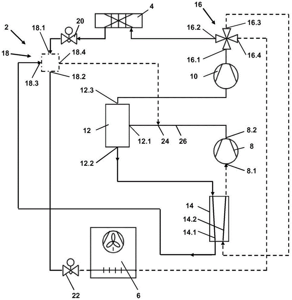
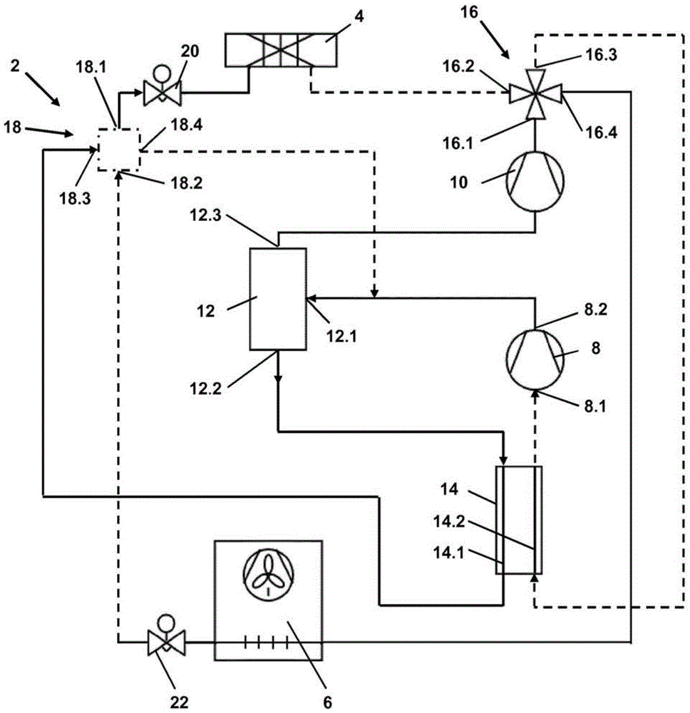
[0031] Figure 1a and 1b Indicates that a heat pump 2 according to the present invention is in heating operation ( Figure 1a ) or in refrigeration work ( Figure 1b ). In the circuit diagrams shown, the different phase states or pressure levels of the medium or refrigerant are represented by different connection types. Basically three different states occur in the heat pump according to the invention: firstly the refrigerant or the medium is delivered partly in liquid state, which is indicated by the solid line. Furthermore, the medium is partly delivered as cold gas, which is indicated by the dotted connection. Furthermore, the medium is also conveyed as hot gas, which is indicated by a dotted connection. The direction of flow is indicated by arrows.

[0032] The heat pump 2 according to the invention has a first heat exchanger 4 which can be formed as a plate heat exchanger. This first heat exchanger 4 is connected to the object to be heated or cooled. A second heat e...


PUM


Abstract

The invention relates to a heat pump (2) switchable between cooling operation and heating operation, having: a first heat exchanger (4), a second heat exchanger (6), two for compressing a medium Compressor stage (8,10), an intermediate pressure bottle (12) used for phase separation of liquid medium connected between compressor stage (6,8) and second compressor stage (10); wherein A switching valve (16) is connected downstream of the second compressor stage (8), by means of which a communication between the second compressor stage (8) and the second heat exchanger (6) can be established during refrigeration operation. A flow connection and a flow connection between the second compressor stage ( 8 ) and the first heat exchanger ( 4 ) can be established during heating operation.

Description

technical field [0001] The invention relates to a heat pump switchable between cooling operation and heating operation, the heat pump having a first heat exchanger and a second heat exchanger between which energy can be transferred in one or the other direction , and has a compressor unit. Background technique [0002] Heat pumps of the type mentioned at the outset are known from the prior art. Such a heat pump is used to transfer thermal energy from a first container to a second container while expending work. Heat pumps generally work with a fluid that is evaporated at low pressure with heat input and condensed again with heat output after compression to high pressure. The pressures are chosen such that the temperature of the phase transition has a sufficient difference for the heat transfer relative to the temperature of the heat source or heat sink. [0003] In its simplest form, a heat pump works with a fluid circuit that has: an evaporator in which the fluid or medi...

Claims


Application Information

Patent Timeline
Patent Type & Authority Patents(China)
IPC IPC(8): F25B40/06F25B13/00F25B1/10
Inventor U·克龙斯特伦S·克林克D·普法伊尔
Owner ROBERT BOSCH GMBH
Why Eureka
Try Eureka