Bottle-parison variable-pitch apparatus of bottle blowing machine

A technology of variable pitch and bottle blowing machine, applied in the field of variable pitch devices, can solve the problems of slow action response, asynchronous change of pitch of preforms, increase of reject rate, etc., to avoid sticking, change pitch synchronously, and improve the yield of finished products.

Active Publication Date: 2014-11-05
JIANGSU FEIGE YOULIAN MACHIMERY
View PDF2 Cites 5 Cited by
  • Summary
  • Abstract
  • Description
  • Claims
  • Application Information

AI Technical Summary

Problems solved by technology

This structure requires a cylinder with a very large stroke to complete the above actions. At the same time, the variable pitches of several preforms are not synchronized, and there is a time difference between them. The time difference between the first preform and the last preform is the largest, which will cause the heated bottle Sticking between blanks, the movement is not smooth, resulting in an increase in the scrap rate
The preform slides, and the guide head at the lower end of the push rod needs to move down and insert into the preform mouth, so as to drive the preform to slide on the guide rail to change the pitch. After the variable pitch is completed, it needs to move up and separate from the preform mouth. The movement is realized by the cylinder driving the preform variable pitch mechanism of the blow molding machine to move up and down, and the action response is slow and the efficiency is low
[0004] The disadvantages of the preform variable pitch mechanism of the above blow molding machine are: the time difference of the preform variable pitch will cause the heated preform to stick, the motion will not be smooth and the waste will increase, and the push rod guide head will take time to insert into the preform mouth and the efficiency will be low.

Method used


Image

  • Bottle-parison variable-pitch apparatus of bottle blowing machine
  • Bottle-parison variable-pitch apparatus of bottle blowing machine
  • Bottle-parison variable-pitch apparatus of bottle blowing machine

Examples


Embodiment Construction

[0024] The present invention will be described in further detail below through specific examples.

[0025] The upstream and downstream described in this embodiment are determined by the running direction of the preform 6, as figure 1 As mentioned above, the left side of the diagram is downstream, and the right side is upstream.

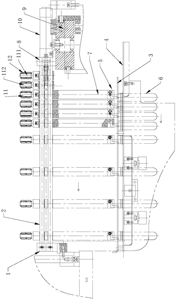
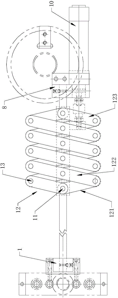
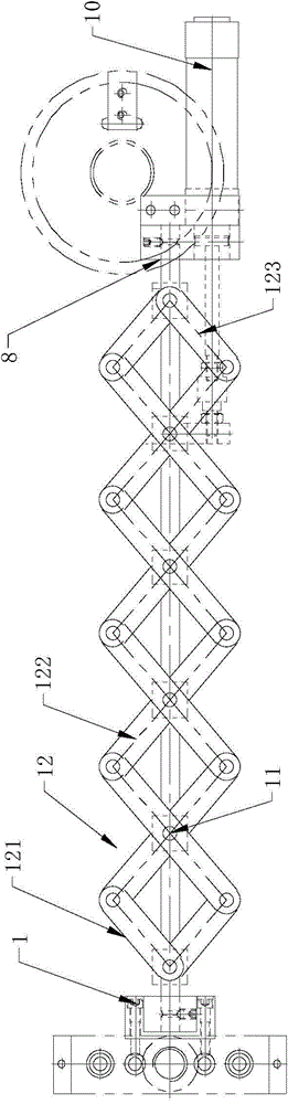
[0026] Such as figure 1 , 2 , 3 and 6, a bottle blank variable pitch device for bottle blowing machine, the variable pitch device is installed between the outlet of the heating device of the bottle blowing machine and the blowing mold, the variable pitch device includes guide rods 2, several Connecting rod 12, several push rods 7, several sets of preform clamping mechanisms 5, linear drive device 10. After the preform 6 is heated in the heating box, it will be led out through the guide plate 4. The guide plate 4 is provided with a guide groove to facilitate the sliding of the preform 6. The preform 6 is in the guide groove and the annular convex ed...


PUM


Abstract

A disclosed bottle-parison variable-pitch apparatus of a bottle blowing machine comprises a guide rod, multiple connection rod, multiple push rod, multiple bottle-parison clamping mechanisms and a linear driving device; the guide rod is installed on a rack of the bottle blowing machine; the push rods are installed on the guide rod along the axial direction of the guide rod in a slidable way; the lower end of each push rod is provided with one bottle-parison clamping mechanism; the middle parts of the connection rods are in paired mutual hinge connection via a middle hinge shaft; two ends of each connection rod are respectively hinged to corresponding ends of an adjacent connection rod via a side hinge shaft; the multiple connection rods form multiple sequentially-connected equilateral rhombuses together-used by apexes; a first middle hinge shaft closest to a heating device is fixedly disposed on the rack, and other middle hinge shafts are in one-to-one corresponding fixing connection with the push rods; and the linear driving device is fixedly disposed on the rack and is connected with the middle hinge shafts or the push rods. The variable-pitch apparatus is capable of synchronously changing the pitch of a bottle parison without time difference, the adhesion phenomenon of adjacent heated bottle parisons caused by time difference during changing of pitch of bottle parisons is avoided, and the finished-product rate of the product is improved.

Description

technical field [0001] The invention relates to a variable pitch device, in particular to a bottle blank variable pitch device for a bottle blowing machine. Background technique [0002] In recent years, China's beverage industry has developed rapidly, and it has driven the rapid development of beverage machinery. The blow molding machine is a commonly used machine for producing beverage bottles in beverage machinery factories, and the heating energy consumption of the blow molding machine is the entire production line. The largest part of the blow molding machine, the traditional blow molding machine does not have a variable pitch device, the distance between the preform seat and the cavity of the mold is equidistant, resulting in a greatly reduced heat utilization rate of the heating lamp tube, through the variable pitch mechanism of the blow molding machine preform can be Realize that when the preform is heated, the distance between the preform and the preform is smaller ...

Claims


Application Information

Patent Timeline
Patent Type & Authority Applications(China)
IPC IPC(8): B29C49/42
Inventor 杨新良谢明飞
Owner JIANGSU FEIGE YOULIAN MACHIMERY
Why Eureka
Try Eureka