Automatic lubrication device of construction lifter

A technology for construction elevators and lubricating equipment, which is applied in the direction of mechanical equipment, engine lubrication, lubricating parts, etc., can solve the problems of waste, electricity and oil, slow work efficiency, etc., and achieves simple and compact structure, extended service life, and convenient installation. Effect

Inactive Publication Date: 2014-12-10
王积文
View PDF16 Cites 9 Cited by
  • Summary
  • Abstract
  • Description
  • Claims
  • Application Information

AI Technical Summary

Problems solved by technology

There are generally two types of lubrication in the past: one is traditional manual lubrication, which works by standing on the top of the construction elevator car and applying lubricating oil piece by piece with bare hands. The disadvantage is that the work efficiency is slow, time-consuming, and prone to falling. There is a major safety hazard
One is mechanical lubricating machine lubrication. Its working method is to manually operate the switch button of the oiling machine. People are in the car. Although the potential safety hazard of falling people and objects is solved, the oiling machine needs to be pushed to the bottom when refueling. In the car, the oiler needs to be pushed down the car after refueling. Next time, the oiler needs to be pushed to the car and pushed down the car. In order to reduce the number of times of oiling and prolong the interval of oiling, a The amount of oil is too large, its disadvantages are human factors, and the power is large, the amount of oil is too large, it consumes electricity and oil, and the splash is serious, causing unnecessary waste

Method used


Image

  • Automatic lubrication device of construction lifter
  • Automatic lubrication device of construction lifter
  • Automatic lubrication device of construction lifter

Examples


Embodiment Construction

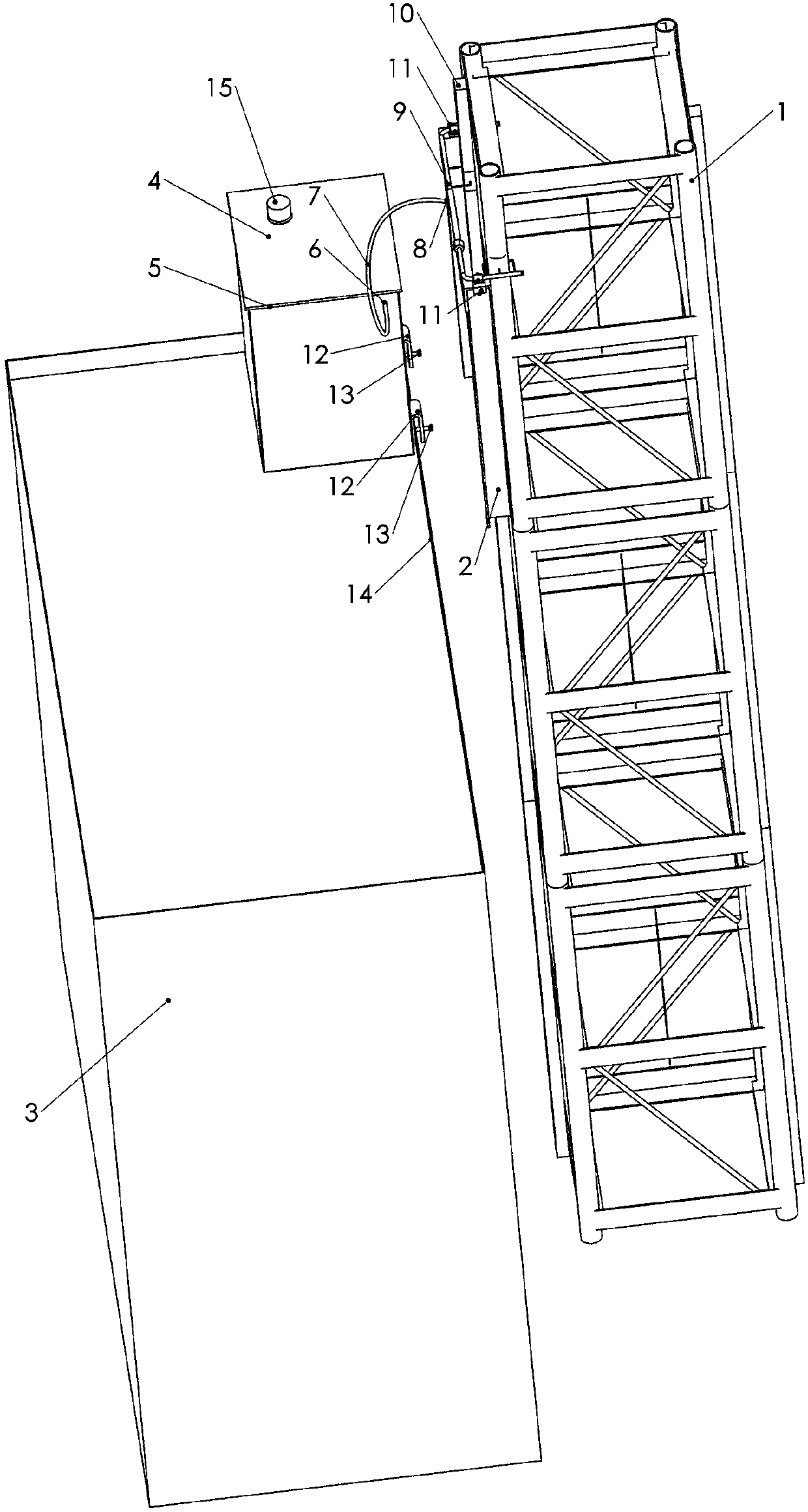
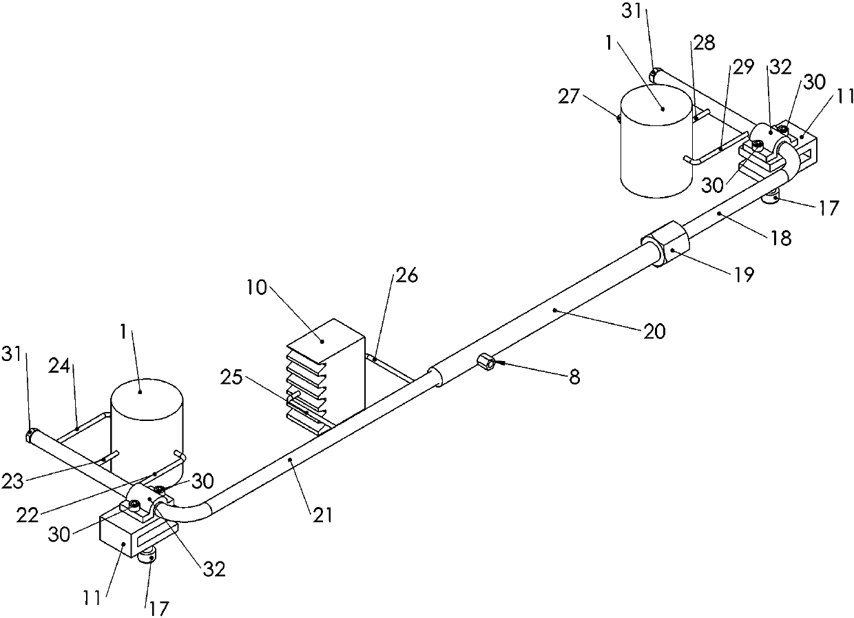
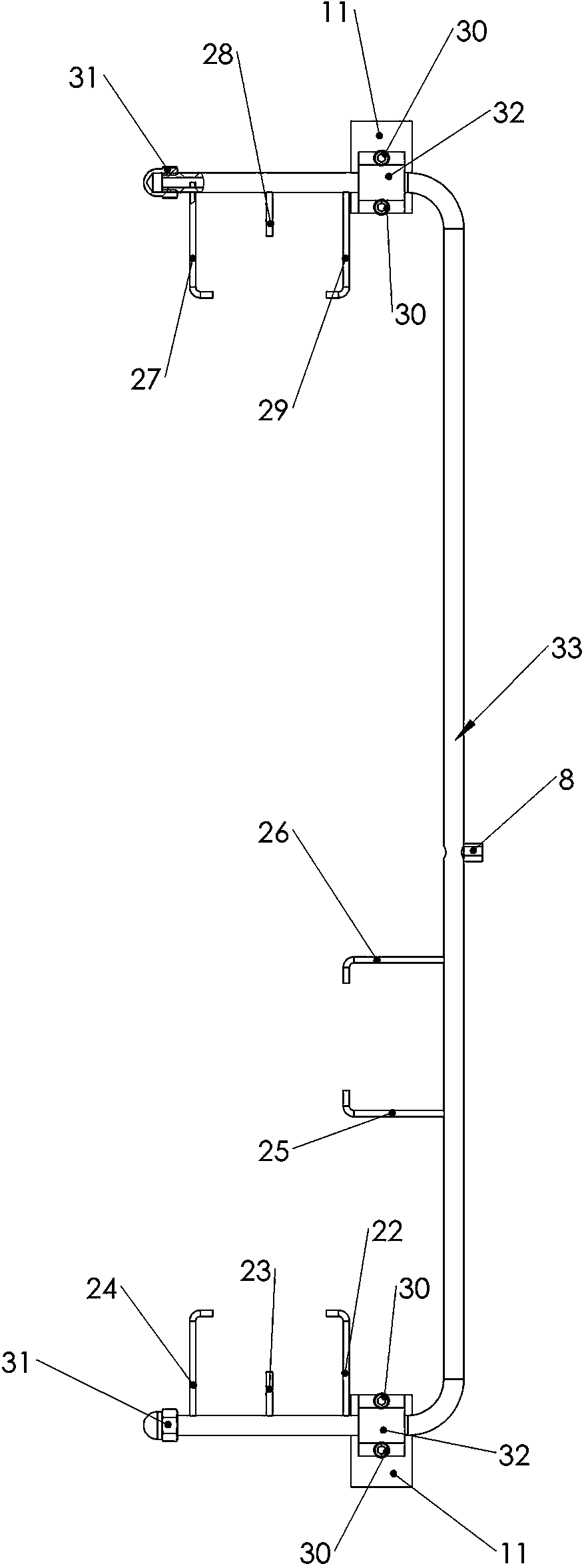
[0027] figure 1 , figure 2 , Figure 4 , Figure 8The lubricating equipment for a construction elevator shown includes a fuel tank 4, a fuel tank filler cap 15, a fuel tank filler hole 16, an oil pump motor 41, an oil pump 32, and an oil outlet pipe 36. The oil pump motor 41 is connected to the oil pump 32, and is characterized in that: The oil tank 4 has a first chamber 46 and a second chamber 45; the oil pump motor 41 is in the second chamber 45; Composition, the left oil distribution rack pipe 21, the right oil distribution rack pipe 18 and the telescopic sleeve 20 are hollow pipes, one end of the left oil distribution rack pipe 21 is connected to the telescopic sleeve 20 end, and the right oil distribution rack pipe 18 is stretched Sliding fit in the sleeve 20, the end of the telescopic sleeve 20 close to the right oil distribution rack pipe 18 is provided with a thread and a joint nut 19 matched with this thread, and a sealing sleeve 53 matched with the joint nut 19 i...


PUM


Abstract

The invention relates to a lubrication device of a construction lifter. An oil tank (4) is provided with a first chamber (46), a second chamber (45), a U-shaped clamp (12) and a rainproof edge (5). An oil distribution frame device (9), for example, a hollow pipe which is stretchable in length or is provided with an integrated oil distribution frame clamp (11), is arranged, and the oil distribution frame device is provided with the oil distribution frame clamp (11) and multiple oil distribution pipes, and can be also provided with a hairbrush. A control system which can be composed of a micro processing controller, a large-power driving element and a sensor or composed of a voltage sensor, a counter and a timer is arranged, and the control system drives the large-power driving element to control an oil pump motor (41). The lubrication device of the construction lifter can effectively prolong the service life of the construction lifter, does not change the structure and rigidity of the exiting construction lifter, does not need to puncture the construction lifter, is convenient to install, and realizes accurate and appropriate lubrication, energy conservation, environment protection, oil and time saving, separation of electricity and oil, rain prevention and dust prevention.

Description

technical field [0001] The invention relates to a lubricating device, in particular to an automatic control lubricating device for a construction hoist guide rail rack. Background technique [0002] Construction hoists are commonly used equipment in engineering buildings, which are exposed outdoors and used in harsh environments. The guide rail rack needs to be lubricated during work. There are generally two types of lubrication in the past: one is traditional manual lubrication, which works by standing on the top of the construction elevator car and applying lubricating oil piece by piece with bare hands. The disadvantage is that the work efficiency is slow, time-consuming, and prone to falling. There is a major safety hazard. One is mechanical lubricating machine lubrication. Its working method is to manually operate the switch button of the oiling machine. People are in the car. Although the potential safety hazard of falling people and objects is solved, the oiling mac...

Claims


Application Information

Patent Timeline
Patent Type & Authority Applications(China)
IPC IPC(8): F16N7/38F16N25/00F16N29/02F16N19/00
Inventor 王积文
Owner 王积文
Why Eureka
Try Eureka