Manipulator structure for automatic polishing production line

An automatic polishing and production line technology, which is applied in the direction of manipulators, program-controlled manipulators, conveyor objects, etc., can solve the problems that have not been seen in the technical inspiration, the labor intensity of operators, and the impact of high-efficiency production, so as to achieve good automation effects and save Labor resources, the effect of realizing human-machine isolation

Inactive Publication Date: 2015-01-07
常熟市隆成无纺机械有限公司
View PDF9 Cites 4 Cited by
  • Summary
  • Abstract
  • Description
  • Claims
  • Application Information

AI Technical Summary

Problems solved by technology

[0004] The above two polishing methods all have the following technical problems: one is that a stainless steel container such as the aforementioned stainless steel pot needs to be polished by a group of polishing machines to complete the polishing of various parts, thus investing a lot of manpower. It is a kind of confusion; the second is that the operator is accompanied by the polishing machine (the industry is accustomed to call it "check-in"), and because the dust generated during the polishing process is serious and the noise emitted by the polishing machine is harsh and weird, so the operator Being harassed by dust and noise, it is very easy to damage the body of the operator; third, due to the low efficiency and high labor intensity of the operator, it has a certain impact on industrialized high-efficiency production; fourth, because the operator is always in contact with the polishing machine As a companion, it is easy to cause accidents if you are not careful
[0005] For the above-mentioned prior art, it is necessary to improve it. For this reason, the applicant has searched the literature, expecting to obtain the enlightenment to solve the above-mentioned technical problems, but there is no corresponding technology in the Chinese and foreign patents and non-patent literatures disclosed so far. enlightenment

Method used


Image

  • Manipulator structure for automatic polishing production line
  • Manipulator structure for automatic polishing production line
  • Manipulator structure for automatic polishing production line

Examples


Embodiment 1

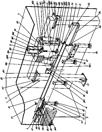
[0025] See figure 1 , a frame 1 is given, and the frame 1 is supported in the polishing machine 8 of the automatic polishing production line in the state of use ( figure 2 with Figure 4 shown) on the ground where the figure 1 As shown, the entire frame 1 is a gantry structure (also described in detail below). A crossbeam automatic lifting mechanism 2 is provided, and the crossbeam automatic lifting mechanism 2 is fixed on the top of the aforementioned frame 1 in a vertical cantilever state. A lifting beam 3 preferably made of a metal tube with a rectangular or square cross-sectional shape is provided, and the lifting beam 3 is fixedly connected to the automatic lifting mechanism 2 of the beam in a horizontal state. A moving beam 4 is provided, which is arranged in a horizontal state and is slidingly fitted with the aforementioned lifting beam 3 . A set of workpiece extracting and releasing mechanisms 5 for extracting workpieces and releasing the extracted workpieces is g...

Embodiment 2

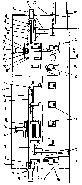
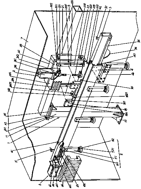
[0041] See Figure 2 to Figure 4 , figure 2 essentially figure 1 expansion, because when there are many polishing stations to the workpiece, that is, the stainless steel pot 10 exemplified above, for example, when the polishing station is five or more, the distance between the left and right columns 11, 12 of the frame is enlarged, and the machine The length of frame frame 13 increases (extends), and the length of dust-proof and noise-reducing compartment 7 is also extended adaptively, and the quantity of equipped polishing machines 8 also increases simultaneously. In view of this situation, in this embodiment 2, the beam automatic lifting mechanism 2, the lifting beam 3, the moving beam 4, a set of workpiece extraction and release mechanisms 5 and the moving beam driving mechanism 6 in the first embodiment are doubled, that is, there are Two sets, taking the moving beam 4 as an example, the two moving beams 4 are connected by an extended fixed connecting plate 44 . Specif...


PUM


Abstract

The invention discloses a manipulator structure for an automatic polishing production line, and belongs to the technical field of automatic polishing facilities. The manipulator structure comprises a rack born on a terrace where the polishing machines of the automatic polishing production line are located, a beam automatic lifting mechanism fixed on the upper portion of the rack, a lifting cross beam connected with the automatic lifting mechanism, a moving beam horizontally arranged and matched with the lifting cross beam, a group of workpiece extraction and release mechanisms arranged on the moving beam, and a moving beam drive mechanism arranged on the lifting cross beam and in transmission connection with the lifting cross beam. The manipulator structure has no need of assigning operating personnel for the working position where each polishing machine is located, as well as is capable of saving labour resources, free from dust and noise influences generated by the polishing machines during a polishing process, good in automation effect, and capable of meeting high-efficiency polishing requirements on the polishing machines and reducing the working intensity of the operating personnel, ensuring safety, and reducing the operating personnel.

Description

technical field [0001] The invention belongs to the technical field of automatic polishing facilities, and in particular relates to a manipulator structure for an automatic polishing production line, which is used for automatically extracting polished workpieces and relaying the polished workpieces from the polishing station where the previous polishing machine is located to The polishing station where the next polishing machine is located is transferred until the polishing station where the last polishing machine is located finishes polishing various parts of the workpiece. Background technique [0002] As known in the industry, polishing can improve the finish of workpieces and products, such as polishing glass molds, which can not only ensure the surface finish of products (glass products) formed by glass molds, but also improve the flow of glass melt in glass molds Effect. Another example is the polishing of utensils such as cooking utensils and catering utensils made ...

Claims


Application Information

Patent Timeline
Patent Type & Authority Applications(China)
IPC IPC(8): B65G47/91B65G47/00B65G43/00B25J9/08B25J9/12
Inventor 王开慧
Owner 常熟市隆成无纺机械有限公司
Why Eureka
Try Eureka