Inverting power supply circulating working power generation device

A technology of inverter power supply and power generation device, which is applied to electromechanical devices, electrical components, etc., can solve the problems of high requirements for supporting facilities, waste of resources, long life of nuclear and nuclear waste radioactivity, etc., and achieves good power generation stability and application scope. The effect of wide, flexible mobility

Inactive Publication Date: 2015-02-25
青海汇诚矿业有限公司 +1
View PDF0 Cites 0 Cited by
  • Summary
  • Abstract
  • Description
  • Claims
  • Application Information

AI Technical Summary

Problems solved by technology

Although wind power and solar power are environmentally friendly, they cannot meet the demand for electricity, and are highly dependent on natural conditions, resulting in poor power generation stability; hydropower is a renewable energy source that has less impact on the environment. In addition to providing cheap power, it can also control Flooding, providing irrigation water, improving river navigation, and at the same time improving the transportation, hydropower supply and economy of the area, etc., but the construction period is long, the cost is high, it needs to rely on special natural environmental conditions, and it also has a greater impact on ecology , vulnerable to wind and water disasters; although thermal power generation can meet the needs of electricity consumption, it requires a lot of waste of resources, large investment, high cost, and a large amount of toxic and harmful gases are emitted, causing serious pollution and not environmentally friendly; and nuclear power, which is called clean energy Although the power generation is large, the impact on the environment is small, and the consumption of resources is small, the corresponding supporting facilities have high requirements. The most deadly thing is that the radioactive "life" of nuclear and nuclear waste is too long. In addition to condensing them into nuclear bombs and detonating them forcibly , humans have no way or ability to control (shorten) its "lifespan"

Method used


Image

  • Inverting power supply circulating working power generation device

Examples


Embodiment Construction

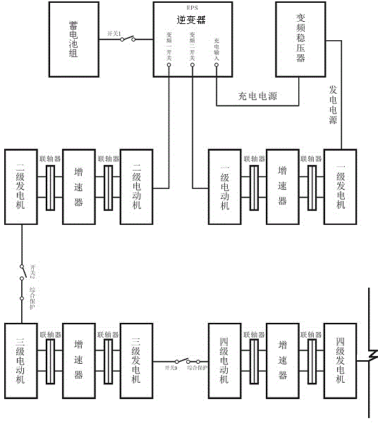
[0025] Below in conjunction with accompanying drawing, technical scheme of the present invention is described in further detail:

[0026] Such as figure 1 As shown, after the battery pack is fully charged with the commercial power, the commercial power is cut off, and the switch 1 is closed to connect the battery power supply of the inverter box. Push the battery switch to let the inverter start to work. After the work is normal, start the primary motor (4.0KW), and drive the primary generator (15KW) to start generating electricity through the coupling and speed increaser. The power generated by the primary generator , after the input frequency conversion regulator stabilizes, it is connected to the charging input port of the inverter to charge the battery pack, and the electricity generated by the battery pack can drive the primary motor to continue to work, thus forming a cycle of work. After the inverter works normally, start the secondary motor (5.5KW), drive the secondar...


PUM


Abstract

The invention relates to the field of power generation equipment, in particular to an inverting power supply circulating working power generation device. The device is characterized in that an inverting power supply drives a first-level power generating device to generate power, the generated power is continuously provided for a storage battery group in the inverting power supply for charging, circulating is formed, meanwhile, the inserting power supply is transmitted to a next-level generating unit, level-by-level transmission is achieved, the power of an electric motor and a power generator is increased level by level, and power generating amount is increased along with increased kinetic energy until a designed terminal is reached. The device is easy and convenient to operate and stable in power supplying, the inserting power supply is controlled by a computer in a micro-electricity mode, protecting is complete, great safety is achieved, and the purpose of low-cost power generating through a multi-level power generating technology is achieved.

Description

technical field [0001] The invention relates to the field of power generation equipment, in particular to an inverter power supply cycle power generation device. Background technique [0002] In Northwest China, the Qinghai-Tibet Plateau, Inner Mongolia grassland pastoral areas, Xinjiang grassland pastoral areas and other remote minority areas, power resources are very scarce, which has caused great difficulties for residents' lives and industrial production. For this reason, many power generation technologies have been developed in our country, such as wind power. Power generation, solar power, hydropower, thermal power and nuclear power, etc. Although wind power and solar power are environmentally friendly, they cannot meet the demand for electricity, and are highly dependent on natural conditions, resulting in poor power generation stability; hydropower is a renewable energy source that has less impact on the environment. In addition to providing cheap power, it can also ...

Claims


Application Information

Patent Timeline
Patent Type & Authority Applications(China)
IPC IPC(8): H02K53/00
Inventor 杨玉宽
Owner 青海汇诚矿业有限公司
Why Eureka
Try Eureka