Multi-stage power generating station

A power station, multi-stage technology, applied in electrical components, electromechanical devices, electric components, etc., can solve the problems of high requirements for supporting facilities, waste of resources, long construction period, etc., to achieve good power generation stability, wide application range, Start the effect of less energy

Inactive Publication Date: 2014-11-12
青海汇诚矿业有限公司 +1
View PDF0 Cites 0 Cited by
  • Summary
  • Abstract
  • Description
  • Claims
  • Application Information

AI Technical Summary

Problems solved by technology

Although wind power and solar power are environmentally friendly, they cannot meet the demand for electricity, and are highly dependent on natural conditions, resulting in poor power generation stability; hydropower is a renewable energy source that has less impact on the environment. In addition to providing cheap power, it can also control Flooding, providing irrigation water, improving river navigation, and at the same time improving the transportation, hydropower supply and economy of the area, etc., but the construction period is long, the cost is high, it needs to rely on special natural environmental conditions, and it also has a greater impact on ecology , vulnerable to wind and water disasters; although thermal power generation can meet the needs of electricity consumption, it requires a lot of waste of resources, large investment, high cost, and a large amount of toxic and harmful gases are emitted, causing serious pollution and not environmentally friendly; and nuclear power, which is called clean energy Although the power generation is large, the impact on the environment is small, and the consumption of resources is small, the corresponding supporting facilities have high requirements. The most deadly thing is that the radioactive "life" of nuclear and nuclear waste is too long. In addition to condensing them into nuclear bombs and detonating them forcibly , humans have no way or ability to control (shorten) its "lifespan"

Method used


Image

  • Multi-stage power generating station
  • Multi-stage power generating station

Examples


Embodiment Construction

[0027] The technical solution of the present invention will be further described in detail below in conjunction with the accompanying drawings:

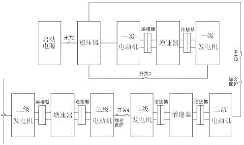
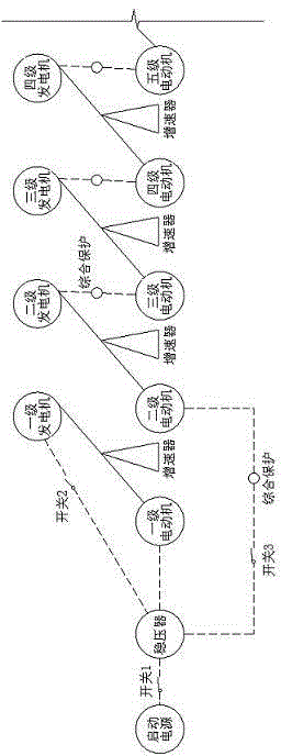
[0028] Such as figure 1 As shown, start the 8.0KW diesel generator set to supply power, the input voltage of 380V enters the 30KW regulator, and the output 380V three-phase power. Close switch 1, the 4.0KW first-stage motor starts to work, generates mechanical kinetic energy, and is electrically connected to the speed increaser through the connector, and drives a 15KW first-stage generator to work, generating electricity with a voltage of 380V and a power of 15KW. After running for 1 minute Close switch 2, and output the electric energy generated by the first-stage generator set through the voltage stabilizer. After the voltage and current are stable, immediately cut off switch 1 to form a smooth switch between the first-stage generator power supply and the start-up power supply. After reaching the cycle of work, close switch 3 and Thro...


PUM


Abstract

The invention relates to the field of power generating equipment, in particular to a multi-stage power generating station. The multi-stage power generating station is mainly characterized in that an energy source is started to drive a power generating unit to generate energy circulation, generated electric energy is transmitted to a power generating unit of the next stage, the electric energy is transmitted stage by stage, power of a motor and power of power generators are increased stage by stage, and the power generating amount is increased along with gradual increase of the kinetic energy until a design terminal is reached. The multi-stage power generating station saves energy, is low in carbon and environmentally friendly, and multi-stage power generation can meet different power utilization requirements; the multi-stage power generating station is free from the influence of the natural conditions, good in power generating stability, easy to install, overhaul and maintain, suitable for various geographical environments, high in scale controllability, low in power generation cost, capable of generating power in a moving mode, high in flexible maneuverability, and wide in application range.

Description

Technical field [0001] The invention relates to the field of power generation equipment, in particular to a multi-stage power station. Background technique [0002] In Northwest China, the Qinghai-Tibet Plateau, Inner Mongolia pastures, Xinjiang pastures and other remote ethnic minority areas, electricity resources are very scarce, causing huge difficulties for residents’ lives and industrial production. For this reason, my country has developed many power generation technologies, such as wind power. Power generation, solar power, hydropower, thermal power and nuclear power, etc. Although wind power and solar power generation are environmentally friendly, they cannot meet the demand for electricity, and are highly dependent on natural conditions, and the stability of power generation is poor; hydropower is a renewable energy source and has less impact on the environment. In addition to providing cheap power, it can also be controlled Flooding, the provision of irrigation water, t...

Claims


Application Information

Patent Timeline
Patent Type & Authority Applications(China)
IPC IPC(8): H02K7/20
Inventor 杨玉宽
Owner 青海汇诚矿业有限公司
Why Eureka
Try Eureka