Method for preparing ammonia gas from urea solid by dry pyrolysis

A technology of urea and solid, which is applied in the field of urea solid dry pyrolysis to produce ammonia, which can solve the problems of large footprint, high cost, steam consumption, etc., and achieve the effects of low moisture content, small footprint, and reduced equipment

Active Publication Date: 2010-10-27
中建中环新能源有限公司
View PDF3 Cites 15 Cited by
  • Summary
  • Abstract
  • Description
  • Claims
  • Application Information

AI Technical Summary

Problems solved by technology

[0007] (1) Both the dissolution and solution storage of urea need to be equipped with corresponding devices and auxiliary equipment, and additional consumption of steam is required, the process is complicated and the floor area is large;
[0008] (2) The urea solution is easy to crystallize, and all relevant containers and pipelines must be heated to keep the temperature above the corresponding crystallization temperature, and the urea solution is corrosive to a certain extent, and has high requirements for the materials of equipment and pipelines;
[0009] (3) In addition to the energy consumption of urea decomposition in the pyrolysis process, the evaporation of water in the solution also requires a lot of energy. In order to meet these energy consumption requirements, the high-temperature air temperature is generally controlled above 600°C, and the material of the electric heater needs to be high-temperature-resistant. Alloy steel, the cost is greatly increased;
[0010] (4) The water used to dissolve urea has strict requirements and must be pure water (condensed water, desalted water); if pure water is not used, corresponding additives must be used to stabilize it, because impure water will cause the denitrification catalyst to block And sulfur / metal poisoning, etc., thereby shortening the life of the catalyst, increasing the consumption of reducing agents, and increasing the investment cost; and the generated pyrolysis gas contains excess water vapor, which has a certain inhibitory effect on the denitrification efficiency

Method used


Image

  • Method for preparing ammonia gas from urea solid by dry pyrolysis
  • Method for preparing ammonia gas from urea solid by dry pyrolysis
  • Method for preparing ammonia gas from urea solid by dry pyrolysis

Examples


Embodiment

[0030] Below in conjunction with certain 50MW engineering flue gas denitrification project, the present invention is further described:

[0031] Original design data: The flue gas volume of this project is 211600Nm 3 / h, the smoke temperature is 320°C, the water vapor content is 9%, the denitrification efficiency is 48%, the ammonia escape rate is 3ppm, and the urea nitrogen content is 46%.

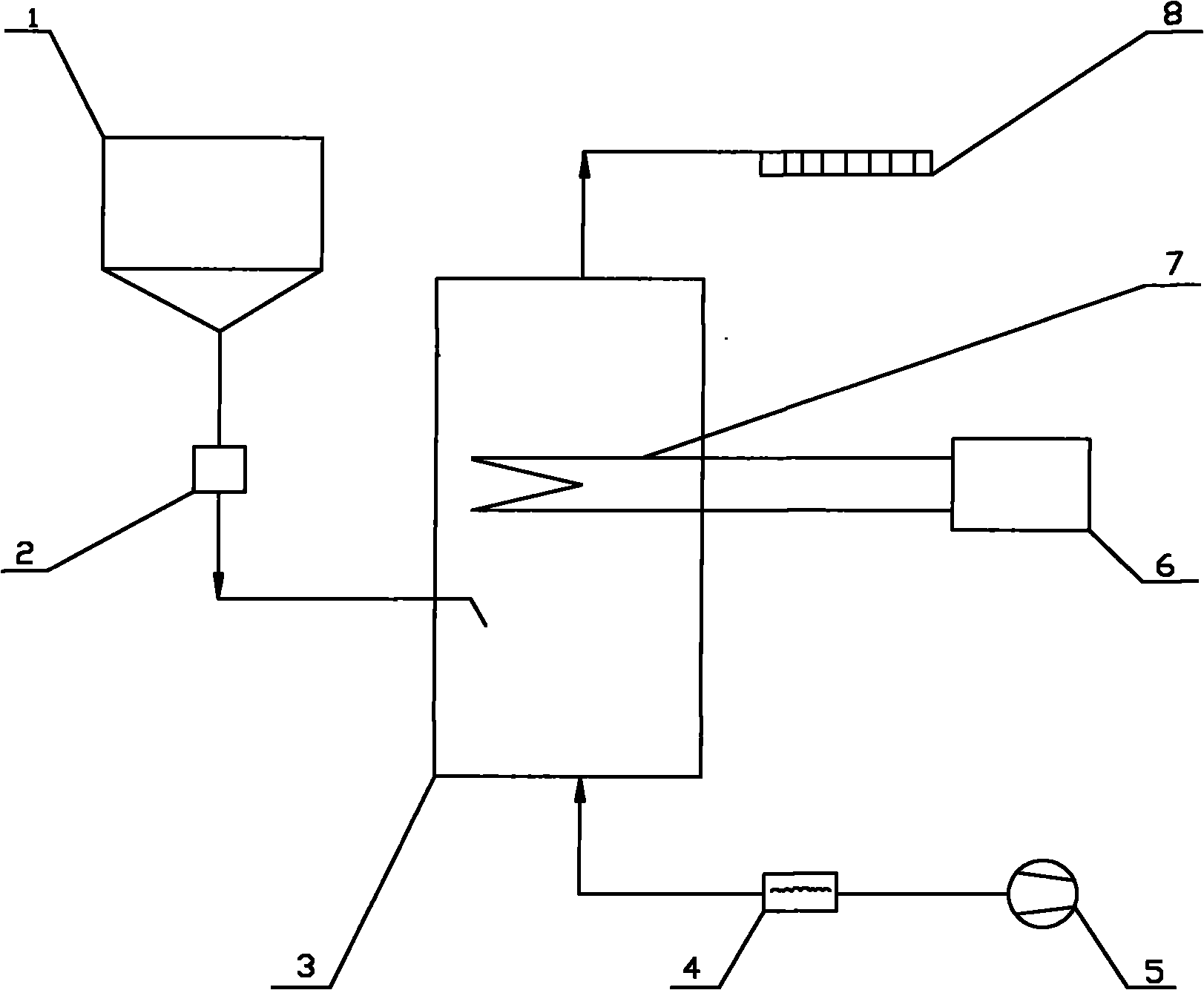
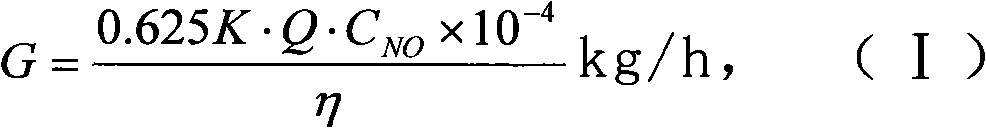
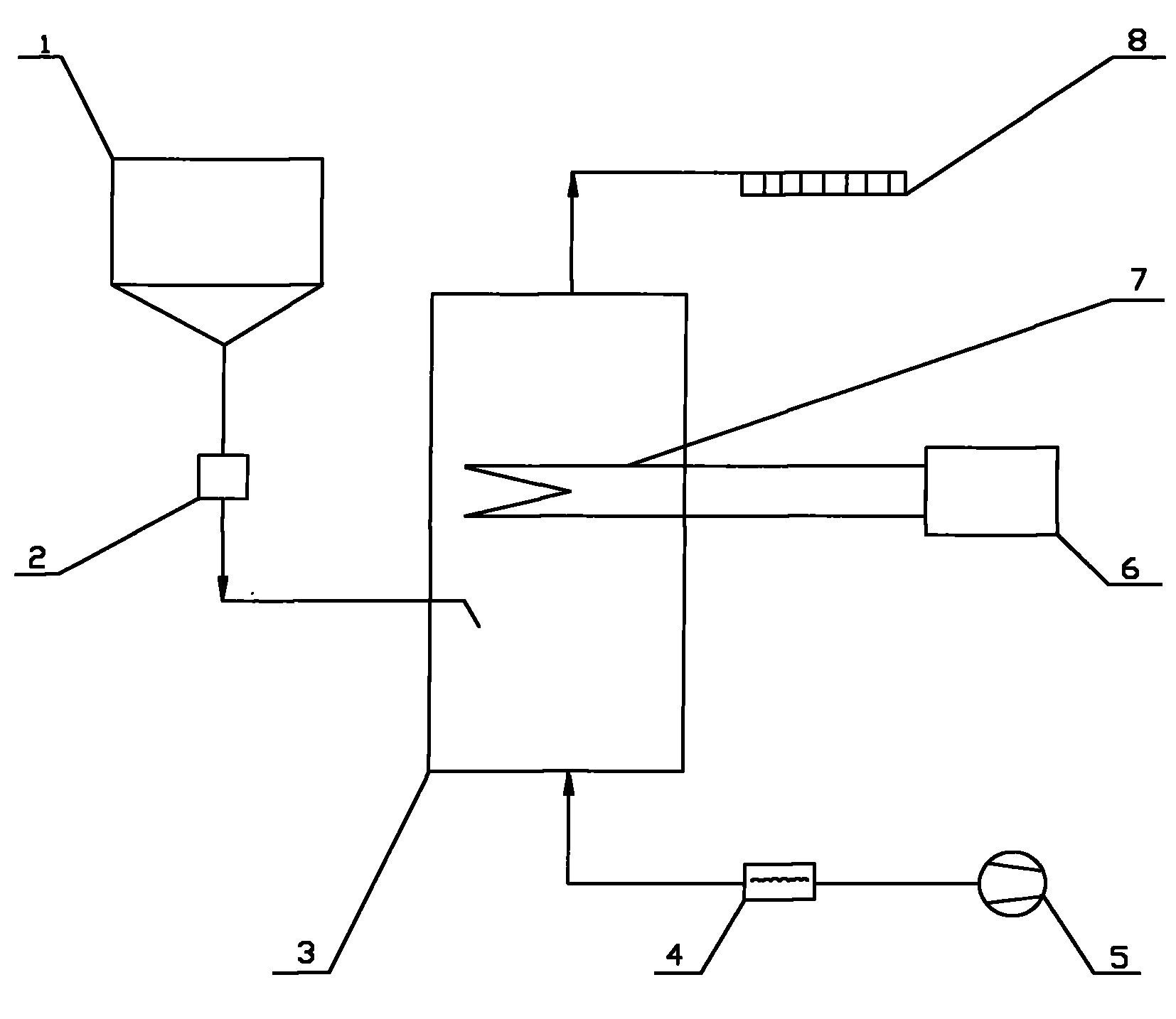
[0032] (1) The urea solid in the urea solid storage tank 1 is transported into the pyrolysis furnace 3 by the metering and feeding device 2 . The amount of urea added is based on the load signal of the denitrification unit and the NO x Feedback real-time control of the analyzer or CEM system. The calculation formula is:

[0033] G = 0.625 K · Q · C NO × 10 - ...


PUM


Abstract

The invention discloses a method for preparing NH3 from a urea solid by dry pyrolysis. The method comprises the following steps of: delivering the urea solid into a pyrolysis oven by using a quantitative feeding device, wherein the feeding amount is adjusted corresponding according to actually-measured NOx amount in smoke gas; inputting high-temperature gas delivered by a high-temperature fan into the pyrolysis oven by using a flowmeter, wherein the high-temperature gas is fully contacted with urea; the urea is heated and decomposed into isocyanic acid and ammonia gas; and the isocyanic acid undergoes a further reaction with water vapor in the high-temperature gas so as to generate the ammonia gas and carbon dioxide; and replenishing heat supply when needed by using an electric heater in the pyrolysis oven, wherein pyrolysis gas is taken as a reducing agent used for removing NOx by selective catalyctic reduction and introduced into an ammonia spray grid after being exhausted from the pyrolysis oven. The method has the advantages of elimination of urea dissolving and solution storing steps, no water consumption, low energy consumption in a pyrolytic process, energy supply from a photovoltaic system, simple system technology, small floor area and low running cost.

Description

technical field [0001] The invention relates to a method for producing ammonia by dry pyrolysis of urea solids, specifically pyrolyzing urea solids directly in a pyrolysis furnace to generate NO in flue gas for selective catalytic reduction (SCR) removal X The reducing agent NH 3 , belonging to nitrogen oxides (NO X ) handles fields. Background technique [0002] In the existing coal-fired flue gas to remove NO X Among the technologies, selective catalytic reduction (SCR) is the most efficient denitrification technology and the most mature denitrification technology. Reductant NH in SCR technology 3 There are three main sources of ammonia: liquid ammonia, ammonia water and urea. Liquid ammonia and ammonia water are dangerous goods, and there are strict laws and regulations in the process of storage and transportation. Relatively speaking, urea is a non-toxic and harmless chemical, easy to transport and store, and does not require special safety measures. [0003] The ...

Claims


Application Information

Patent Timeline
Patent Type & Authority Applications(China)
IPC IPC(8): C01C1/08
CPCY02P20/10Y02P20/129
Inventor 黄丽娜卢作基徐晓亮
Owner 中建中环新能源有限公司
Why Eureka
Try Eureka