Al technical title is built by PatSnap Al team. It summarizes the technical point description of the patent document.
A brick laying machine, hand-push technology, applied in the field of human-driven hand-push brick laying machine, can solve the problems of time-consuming, laborious, expensive, high cost, etc., and achieve the effect of simple mechanical structure, no energy consumption, and light weight
Inactive Publication Date: 2014-01-08
QINGDAO UNIV OF SCI & TECH
View PDF5 Cites 14 Cited by
Summary
Abstract
Description
Claims
Application Information
AI Technical Summary
This helps you quickly interpret patents by identifying the three key elements:
Problems solved by technology
Method used
Benefits of technology
Problems solved by technology
At present, brick laying operations on both sides of urban streets, park paths and other places are still completely dependent on pure manual work, which is time-consuming and laborious. At the same time, because my country's labor market is already in an era of shortage of supply, labor costs continue to increase, resulting in the profit of brick laying operations. and output are very low, and the ratio of input to output is much lower than that of other sub-projects
[0003] Existing large-scale automatic paving machines allow workers to quickly pave a road like carpets, but these large automatic paving machines cannot operate on these road sections, and can only be fully utilized in the construction of large squares and wider roads. function, in addition, these large automatic brick laying machines are complex in structure, high in cost and expensive
Method used
Image
Click on the blue label to locate the original text in one second.
Reading with bidirectional positioning of images and text.
Examples
Embodiment Construction
[0016] The present invention will be further described below in conjunction with accompanying drawings and examples.
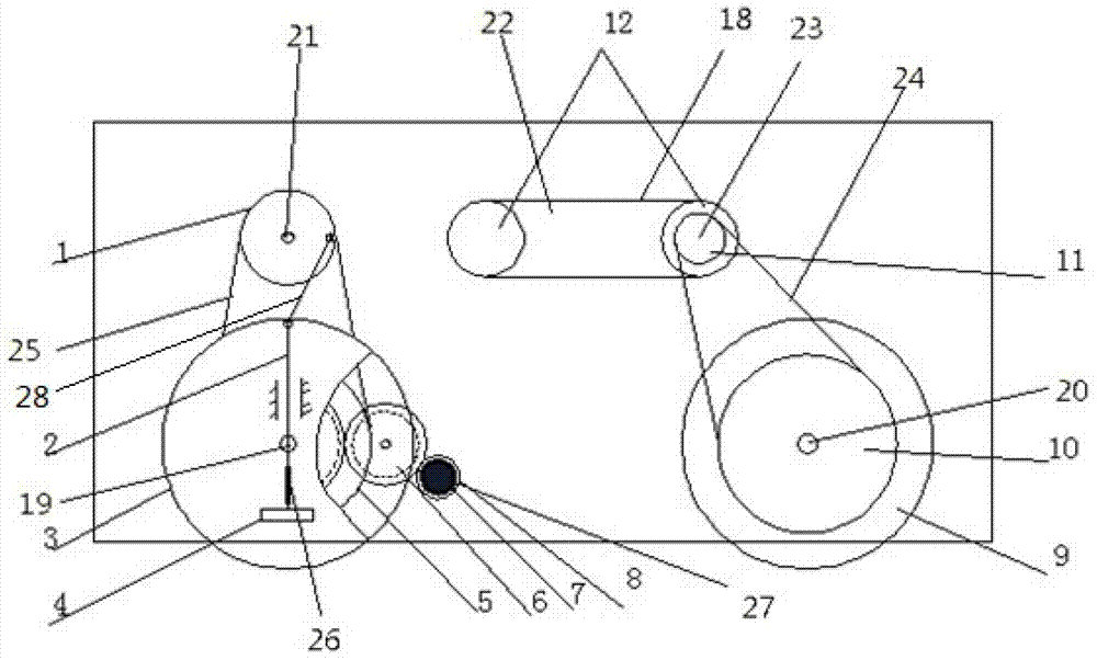
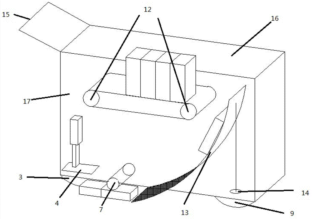
[0017] refer to figure 1 and figure 2 , the hand-push brick laying machine specifically includes 1 body (17), 2 rear wheels (3), 2 front wheels (9), 2 large sprockets (10), 2 small sprockets (11), 2 large pulleys (5), 2 small pulleys (1), 1 conveyor belt (18), 2 rollers (12), 1 brick tray (16), 1 slideway (13), 2 1 rubber roller (7), 1 tamping hammer (4), 1 cover plate, 3 gears of specific size (8), 1 secondary crank slider mechanism (2), 1 rear axle (19), 1 front axle (20), 1 crankshaft (21), 1 bearing plate (22), 1 roller axle (23), 2 direction guide wheels (14).
[0018] The front wheel shaft (20) and the front wheel (9) are interference fit, and are placed on the front and bottom of the body (17); the large sprocket (10) is welded on the connecting shaft between the front wheels (9), and the front wheel (9) Drive the rotation; the small sprocket (11) ...
PUM
Abstract
The invention discloses a hand-push type brick paving machine which mainly comprising a machine body, wheels, a brick loading disc, a conveying belt, a slideway, a friction roller and a compaction mechanism and specifically comprises a small belt wheel, a compaction hammer connecting rod, a rear wheel, a compaction hammer, a large belt wheel, a gear pair, the friction roller, a gear coaxial with the friction roller, a front wheel, a large chain wheel, a small chain wheel, drums, the slideway, a guide wheel, an armrest, the brick loading disc, the machine body, the conveying belt, a rear axle, a front axle, a crankshaft, a bearing plate, a drum shaft, a chain, a triangular belt, a damping spring, a gear shaft and a crank. The machine goes forward when the armrest is pushed, the rotation of the wheels drives the whole machine to act, the conveying belt conveys bricks to the slideway, and the compaction mechanism compacts the bricks and the ground. By adopting the hand-push type brick paving machine disclosed by the invention, the brick paving operation in places such as both sides of an urban street and park paths can be finished simply by manually placing the bricks on the conveying belt of the machine and pushing the machine to go forward, and the problems that an existing brick paving machine is complicated in interior structure and high in cost and cannot be used for paving a sidewalk road and the like are solved.
Description
Technical field [0001] The invention relates to the field of construction machinery, in particular to a human-driven hand-push brick laying machine for laying bricks on both sides of city streets, park paths and other places. Background technique [0002] In urban construction, the construction of pedestrian roads is also an important part of the construction of roads, parks and squares. The main engineering volume of pedestrian road construction is concentrated on brick laying operations. With the acceleration of my country's urbanization process and the construction of small towns, the number of sidewalks, squares, and parks in cities and towns is increasing, and the amount of brick-laying projects is also increasing. At present, brick laying operations on both sides of urban streets, park paths and other places are still completely dependent on pure manual work, which is time-consuming and laborious. At the same time, because my country's labor market is already in an er...
Claims
Application Information
Patent Timeline
Application Date:The date an application was filed.
Publication Date:The date a patent or application was officially published.
First Publication Date:The earliest publication date of a patent with the same application number.
Issue Date:Publication date of the patent grant document.
PCT Entry Date:The Entry date of PCT National Phase.
Estimated Expiry Date:The statutory expiry date of a patent right according to the Patent Law, and it is the longest term of protection that the patent right can achieve without the termination of the patent right due to other reasons(Term extension factor has been taken into account ).
Invalid Date:Actual expiry date is based on effective date or publication date of legal transaction data of invalid patent.